Allied Telesis SwitchBlade 4000 Series Switch Hardware Reference User Manual
Page 42
42
SwitchBlade 4000 Series Switch
C613-03060-00 REV H
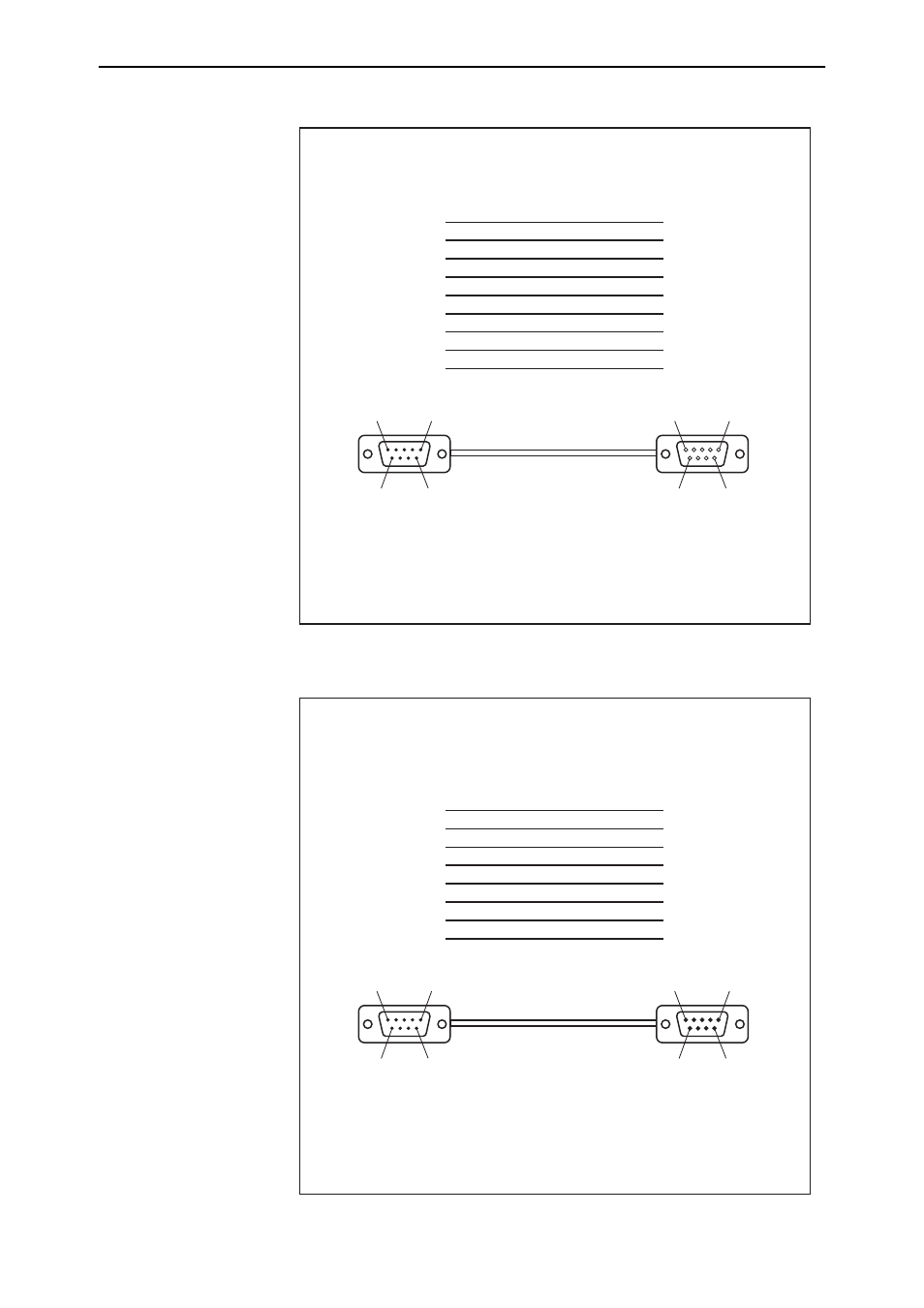
Figure 4: Pin wiring diagram for a standard DB9 male to female terminal cable.
Figure 5: Pin wiring diagram for a DCE RS-232 Terminal Port (DB9 female
connector) male to male modem cable.
Notes:
(1)
→
Output from switch;
←
Input to switch.
(2)
Cable version 1.0.
DB9MDB9Fsw
1
2
3
4
5
6
7
8
9
1
2
3
4
5
6
7
8
9
Cable
Pin 9
Pin 6
Pin 5
Pin 1
DB9 Female Pin View
Pin 6
Pin 9
Pin 1
Pin 5
DB9 Male Pin View
DB9 Male
(to switch/DCE)
DB9 Female
(to PC/terminal/DTE)
Not connected
→ (
TXD)
← (
RXD)
← (
CD)
(GND)
→
(DTR)
←
(CTS)
→
(RTS)
←
(RING)
(DCD)
(RXD)
(TXD)
(DTR)
(GND)
(DSR)
(RTS)
(CTS)
(RING)
Notes:
(1)
→
Output from switch;
←
Input to switch
(2)
Cable version 1.0.
DB9MDB9Fsw
3 (TXD)
2 (RXD)
1 (DCD)
5 (GND)
4 (DTR)
8 (CTS)
7 (RTS)
9
6
Not connected
1
2
3
4
5
6
7
8
9
Cable
Pin 9
Pin 6
Pin 5
Pin 1
DB9 Male Pin View
Pin 6
Pin 9
Pin 1
Pin 5
DB9 Male Pin View
DB9 Male
(to switch/DCE)
DB9 Male
(to modem/DCE)
Not connected
→ (
TXD)
← (
RXD)
← (
CD)
(GND)
→
(DTR)
←
(CTS)
→
(RTS)
(RING)