At-sb4211 and at-sb4211 v2, switch controller, See “at-sb4211 and at-sb4211 v2, switch controller, Weight – Allied Telesis SwitchBlade 4000 Series Switch Hardware Reference User Manual
Page 22: Leds, Switching core, Processing core, Asynchronous serial configuration port
22
SwitchBlade 4000 Series Switch
C613-03060-00 REV H
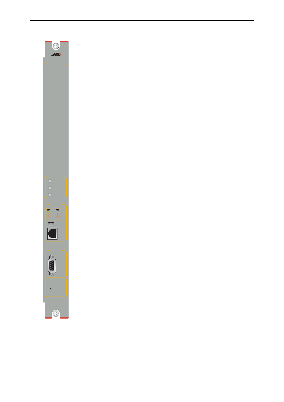
AT-SB4211 and AT-SB4211 V2, Switch Controller
Weight
•
2.5 kg
LEDs
•
Three system status and fault LEDs, and two LEDs to indicate status of
the ETH0 management port (link activity, full/half-duplex, and
collisions)
For a complete list of LEDs and their functions, see “LEDs and What They
Mean” on page 47.
Switching Core
•
Two Application-Specific Integrated Circuit (ASIC) switch chips per
switch controller
•
Non-blocking L2 and L3 IP Switching (may require two switch
controllers to be installed for some chassis configurations)
•
104 k entry forwarding address database
•
128 MByte RAMBUS packet buffer
Processing Core
•
500 MHz PowerPC Processor
•
1 Mbyte of external L2 cache
•
256 MBytes Synchronous DRAM
•
64 bit memory width
•
32 MBytes flash memory
•
512 kBytes Non-volatile Storage SRAM (NVRAM)
•
Battery backed real time clock (RTC)
Asynchronous Serial Configuration Port
•
Up to 115 kbps
•
Standard DB9 female RS-232 connector
•
Hardware or software flow control
10/100BASE-TX Management Port
•
10/100BASE-TX MDI port with RJ-45 connector
•
LEDs indicate link activity, full/half-duplex, and collisions
POWER
MASTER
FAULT
RESET
STATUS
ETH0
L /A
D/C
HALF DUP
FULL DUP
COLLISION
100M
10M
ACTIVITY
L /A
D/C
ASYN0
AT-SB4211 V2
SWITCH CONTROLLER
MANAGEMENT
RS-232
MANAGEMENT
E10 / 100 BASE-T
AT-SB4211 V2
Line Card