Monitoring the initialization processes, Leds and management software initialization – Allied Telesis FS970M Series User Manual
Page 81
FS970M Series Installation Guide
81
Consider the following items as you power on the switch:
Connecting the two power cords to power sources that are on
different circuits will provide power redundancy to the switch in the
event a circuit fails.
The AT-FS970M/24PS and AT-FS970M/48PS Switches support
370 watts of PoE only when both internal power supplies are
connected to power sources. The switches have a PoE budget of
185 watts if just one power supply is functional. For background
information, refer to “Power Supplies” on page 50.
Refer to “Power Specifications” on page 100 for the power
specifications of the switches.
Warning
Power cord is used as a disconnection device. To de-energize
equipment, disconnect the power cord.
E3
Note
Pluggable Equipment. The socket outlet shall be installed near the
equipment and shall be easily accessible.
E5
Monitoring the
Initialization
Processes
It takes a minimum of forty seconds for the switch to initialize its
management software programs and features, and load the configuration
file. You may monitor the progress of the initialization process by watching
the LEDs on the front panel. Table 15 on page 81 provides the various
LED states and the approximate time intervals of the initialization phases.
The time length of phase 4, loading the configuration file, varies from a few
seconds to a minute, depending on the number and complexity of the
commands in the file. The System LED acts differently depending on
whether the unit is powered on or reset with the RELOAD or RESET
command.
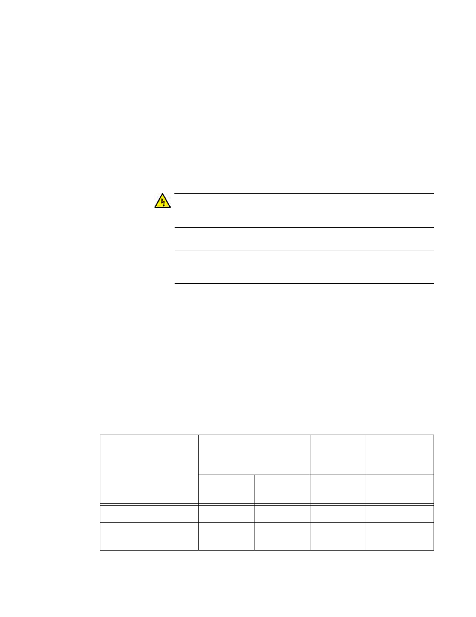
Table 15. LEDs and Management Software Initialization
LEDs
Initialize Management
Software
Initialize
Features
Load
Configuration
File
Phase 1:
15 seconds
Phase 2:
15 seconds
Phase 3:
10 seconds
Phase 4: varies
Base port LEDs
On
On
Off
Off
10/100/1000Base-T port
and SFP slot LEDs
On
Off
Off
Off