Gradient mode parameters, Gradient mode parameters 74 – Campbell Scientific TGA100 Trace Gas Analyzer Manual User Manual
Page 74
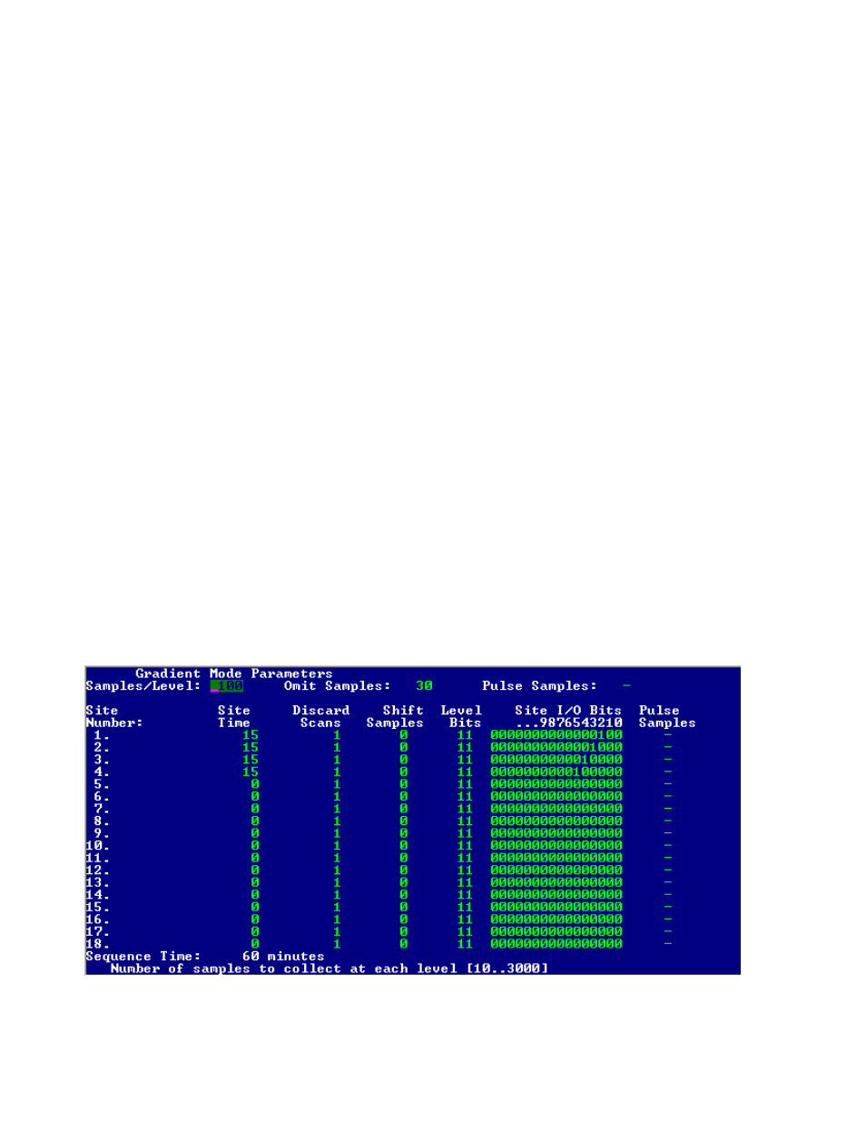
2) In the Gradient Mode Parameters screen, put the following values in the Site Time column: sites (rows) 1, 2, 3,
and 4 should be set to 15 minutes, and all other sites (rows) should be set to zero. This configures the system to
cycle through the four sites once each hour, sampling from each site for 15 minutes.
3) In the Site I/O Bits column, set site (row) 1 to xxxxxxxxxx0001xx, where ‘x’ means it can be either 0 or 1. In the
gradient mode, bits 0 and 1 are designated as the Level Bits, so they must be set as needed to control the gradient
valve assemblies (see section 5.1.4). Bits 6 to 15 are not used in the example, so their setting in this column has no
effect. This setting will cause bit 2 to be activated at the start of the site 1 time and bits 3, 4, and 5 to be inactive
during the site 1 time. Similarly, in row 2 set the Site I/O Bits to xxxxxxxxxx0010xx, row 3 to xxxxxxxxxx0100xx,
and in row 4 to xxxxxxxxxx1000xx. For this example sites 5 through 18 are not active (as selected by putting a
zero in the Site Time column), so the setting of the Site I/O Bits for rows 5 to 18 has no effect.
4) In the Pulse Samples column, set the value for the first four rows to "-", so the site I/O bits will be active for the
duration of the site time. Note that if latching type valves were used, the Pulse Samples column would be set to the
number of samples needed to activate the valves. For this example sites 5 through 18 are not active (as selected by
putting a zero in the Site Time column), so the setting of this parameter for rows 5 to 18 has no effect.
5) Exit the Gradient Mode Parameters screen and go to the Miscellaneous Valve Control screen. In the Invert digital
output bits parameter, set bits 2, 3, 4, and 5 to 0. This is the normal mode (not inverted), so the digital output bits
will be set to a high voltage when active and a low voltage when inactive. Note that bits 0 and 1 of this parameter
must be set as needed for the gradient valve assemblies (see section 5.1.4). Bits 6 through 15 are not used for this
example, so their value has no effect.
When the gradient mode is started by pressing ‘G’ from the real time screen, all four of the gradient valve assemblies
will begin switching between level 1 and level 2 (see section 5.1.4 for instructions on configuring the gradient valve
assemblies). The site selection assembly will connect one of the four sites to the TGA100 sample inlet, as determined
by the real time clock on the TGA PC. The TGA software will synchronize the sampling sequence to the real-time
clock such that a new sequence will begin at midnight. In this example, the duration of the sequence is one hour (15
minutes at each of four sites), so the sequence will be synchronized to switch to site one at the start of each hour.
Generally the first sequence will be shorter than one hour, depending on when the gradient mode is started. If the
gradient mode is started between 0 and 15 minutes past the hour, it will start on site 1. If it is started between 15 and 30
minutes past the hour, it will start on site 2, etc.
5.1.6
Gradient Mode Parameters
Many parameters must be set to control the gradient valves, site selection valves, and calculations. These parameters are
edited at the Gradient Mode Parameters screen, shown in
. Each of these parameters is discussed in this
section.
Figure 5-6. Example Gradient Mode Parameters Screen
74