Controlling a gradient site selection assembly, Controlling a gradient site selection assembly 72 – Campbell Scientific TGA100 Trace Gas Analyzer Manual User Manual
Page 72
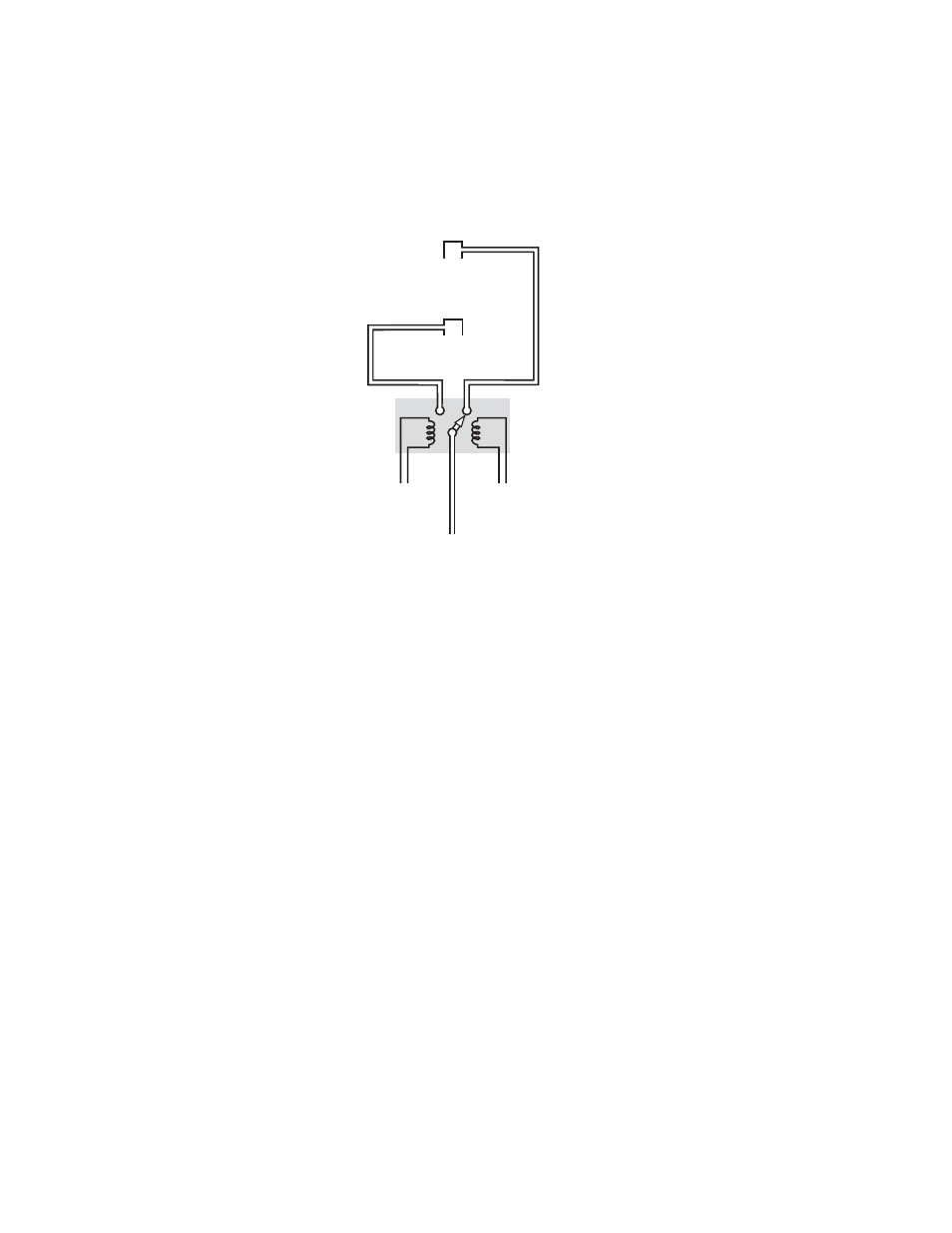
Example 2 illustrates the use of the Pulse Samples and Invert digital output bits parameters (see
). For this
example the gradient valve is a latching type three-way valve. The level 1 intake is connected to valve inlet port 1, the
level 2 intake is connected to valve inlet port 2, and the valve output port is connected to the TGA100 sample inlet. The
valve has two control inputs: A low-voltage pulse on control input 1 will connect port 1 to the output port, and a low-
voltage pulse on input 2 will connect port 2 to the output port. The valve latches onto its new state when switched, so
the control signals do not have to be energized continuously. They only need to be held to a low voltage for 0.2 s to set
the valve state, and then the valve will stay in that state until the other control input is pulsed.
Figure 5-4. Gradient Valve Assembly with a Latching Type 3-Way Valve
Level 2 Intake
Level 1 Intake
To TGA Sample Inlet
To Bit 0
To Bit 1
To configure the TGA100 for this example gradient valve assembly:
1) Connect digital output bit 0 to valve control input 1 and connect bit 1 to valve control input 2.
2) In the top row of the Gradient Mode Parameters menu, set the Samples/Level parameter to the number of samples
to collect at each level. In this example, this parameter is set to 100. This will connect the level 1 intake to the
sample tube for 10 s and then switch to the level 2 intake for 10 s.
3) In the top row of the Gradient Mode Parameters menu, set the Pulse Samples parameter to 2. At the valve
switching time the level bit will be energized for 2 samples (0.2 s) and then turned off.
4) Set the Level Bits for each active site to 11 to enable bit 0 and 1.
5) Set bits 0 and 1 in the Invert digital output bits parameter at the bottom of the Miscellaneous Valve Control menu
to 1, i.e. xxxxxxxxxxxxxx11, where ‘x’ means it can be either 0 or 1. This will invert the bit 0 and 1 output (they
will have a low voltage when active and a high voltage when inactive).
When the gradient mode is started by pressing ‘G’ from the real time screen, digital output bit 0 will be set to a low
voltage for 0.2 s, and then it will return to a high voltage. This control pulse will cause the gradient valve to connect the
level 1 intake to the TGA100 sample inlet. The gradient valve will remain in that state until the start of the Level 2 time,
when digital output bit 1 will be set to a low voltage for 0.2 s. This will switch the gradient valve to connect the level 2
intake to the TGA100 sample inlet. When the gradient mode is turned off by pressing ‘G’ or exiting the real time
screen, bits 0 and 1 will go to a high voltage and the gradient valve will remain in whichever state it is in. Either the
level 1 intake or the level 2 intake will be connected to the TGA100 sample inlet at all times in this example.
5.1.5
Controlling a Gradient Site Selection Assembly
The previous example described a flux gradient measurement at a single site. However, the TGA100 can also support
flux gradient measurements at up to 18 sites. A four-site gradient measurement is illustrated in
. Each of the
four sites has its own pair of air sample intakes (at level 1 and level 2) and its own gradient valve assembly to switch
between the two intakes. All four of the gradient valve assemblies are controlled in parallel: the level 1 intake at each of
the four sites is selected during the level 1 time, and the level 2 intake at each of the four sites is selected during the
level 2 time, regardless of which site is connected to the TGA100. A sample tube from each of the four sites connects
72