4 check the i/o module setup as follows, 3 leds, 1 hdd (hard disk drive) – APC SGI 15000 RAID User Manual
Page 132: Table 8-1 hdd leds, 2 pcm (power cooling module), Table 8-2 pcm leds, 3 dem (drive expander module), Hdd (hard disk drive), Pcm (power cooling module), Dem (drive expander module)
118
007-5510-002
3
Check that there is a valid SAS signal present at the I/O connector. If there is no signal present, ensure
the cable has been properly inserted.
4
Check the I/O module setup as follows:
– Ensure the I/O module has been correctly installed and all external links and cables are securely
fitted.
– Ensure the maximum cable length has not been exceeded.
8.3 LEDs
Green LEDs are always used for good or positive indication. Amber LEDs indicate there is a critical
fault present within the module. See specific LED tables for further information.
8.3.1
HDD (Hard Disk Drive)
When a HDD is faulted,
describes the fault LED behavior.
• Under Normal conditions, the LEDs should all be illuminated constant GREEN.
• If a problem is detected, the color of the relevant LED will change to AMBER.
8.3.2
PCM (Power Cooling Module)
The PCM LEDs are shown in
.
• Under Normal conditions, the LEDs should all be illuminated constant GREEN
• If a problem is detected, the color of the relevant LED will change to AMBER.
8.3.3
DEM (Drive Expander Module)
The DEM fault LEDs are explained in
.
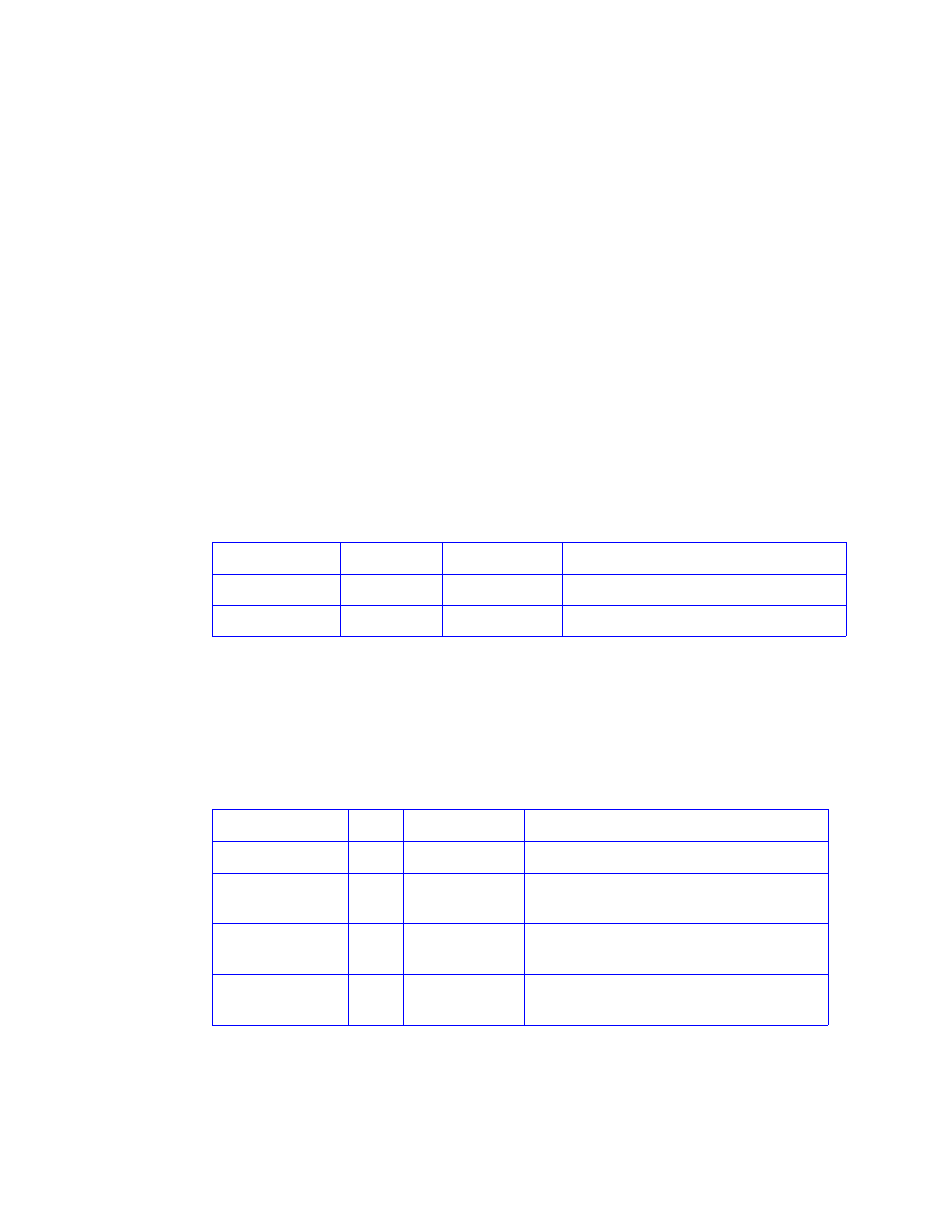
Table 8–1
HDD LEDs
Location
Color
Identifier
Behavior
Enclosure front
Amber
Enclosure fault
This LED is ON with a drive fault
Enclosure front
Amber
Drive fault
This LED is ON with a drive fault
Table 8–2
PCM LEDs
Location
Color
LED Identifier
Behavior
FRONT Enclosure
Amber Enclosure fault
This LED is ON with a PCM fault.
REAR Enclosure
PCM
Amber PCM fault
This LED is ON with an AC input, DC output,
fan or other PCM fault.
REAR Enclosure
PCM
Green
AC OK
This LED is ON with a DC or fan fault.
This LED is OFF with an AC input failure.
REAR Enclosure
PCM
Green
DC OK
This LED is ON with an AC or fan fault.
This LED is OFF with an DC output failure