DME VCTB-4000 User Manual
Page 8
D-M-E Company
VCTB-4000
Page 8
ED-0109-OT-024-( Preliminarry Rev E)
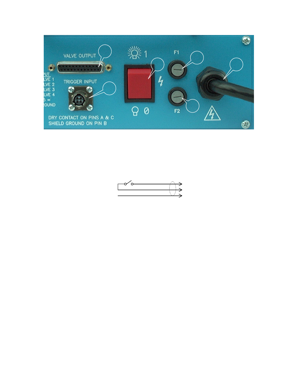
NOTE: TRIGGER INPUT #5 (Customer Connection to Trigger signal dry contact – Injection Forward)
Note: Valve Output Valve # 4 Above
PINS 1, 2, 3 and 4 supply +24 VDC Control power to valves 1, 2, 3 and 4, respectively. PIN 13 supplies
ground to all of the valves.
TOP PLATE
1. Power switch
2. Main Fuses: replace with
Bussman ABC-3 only!
3. Power Entry Cord
4. Valve Output Connector
5. Trigger Signal Input
2
1
2
3
4
5
A
C
B
Trigger Signal Connection
Black
Red
Shield
See also other documents in the category DME Hardware:
- 250 Series Point Gate Needle (2 pages)
- 375 Series Extended Sprue Gate Nozzle (2 pages)
- 375 Series Ring Gate Nozzle (2 pages)
- 625 Series Ring Gate Nozzle (2 pages)
- 375 Series Front Load Heater (2 pages)
- 625 Series Tip Sub-Assemblies (2 pages)
- Integrally Heated Sprue Bushings - 750 SERIES (2 pages)
- Black & Gold Side Interlocks (Metric) (2 pages)
- Black & Gold Top Interlocks (Metric) (2 pages)
- CVe Monitor (1 page)
- IN2 Interlocks (2 pages)
- Toggle-Lok (Positive early ejector return) (3 pages)
- Toggle-Lok (Positive early ejector return) (5 pages)
- 250 Series (2 pages)
- Hydraulic Locking Core Pull Cylinders (12 pages)
- Auto-Fixed Finless Probe (2 pages)
- Auto-Fixed Integral Heater Micro (2 pages)
- Front Load Square Coil Heater (2 pages)
- Stellar with high performance heater (2 pages)
- Chill Vents (2 pages)
- DMAX 625 Series High Performance (2 pages)
- E-Series Straight Shot Hot Sprue Bushings (2 pages)
- ER-Series Straight Shot Hot (2 pages)
- Gate Mate Tip (2 pages)
- Gate-Mate Bushing Assemblies (2 pages)
- Gate-Mate Bushing Sub-Assemblies (2 pages)
- Gate-Mate Nozzle (2 pages)
- Heated Nozzle Locator (2 pages)
- Jumbo Gate-Mate Nozzle (2 pages)
- Global Thinswitch (2 pages)
- Micro Series Distributor Tubes (2 pages)
- Standard Bayonet Thermocouples (2 pages)
- Thinswitch (2 pages)
- Collapsible Cores (1 page)