Emc-3 controller module, Emc‐3 connector designation tables, User guide – rev a – High Country Tek emc-3 User Manual
Page 9
Page 9 of 39
emc-3 Controller Module
User Guide – Rev A
PIN
Name
Function
PIN
Name
Function
PIN
Name
Function
A1
RXD
Receive RS232 Data ‐ Pin 'A'
D2
Uni‐2
Universal Input #2
G3
GND
Ground / 0V / Signal Common
A2
TXD
Transmit RS232 Data ‐ Pin 'C'
D3
GND
Ground / 0V / Signal Common
H1
Dig3
Digital Input #3
A3
RTS
Request To Send ‐ RS232 Pin 'D'
E1
Vref
+5V regulated user output
H2
Ana3
Analog input #3
B1
CAN‐H
CAN #1 High
E2
Uni‐3
Universal Input #3
H3
GND
Ground / 0V / Signal Common
B2
CAN‐L
CAN #1 Low
E3
GND
Ground / 0V / Signal Common
J1
Dig4
Digital Input #4
B3
COM
0V/COM RS232 Data ‐ Pin 'B'
F1
DIG‐1
Digital Input #1
J2
Dig5
Digital Input #5
C1
CAN‐H
CAN #2 High
F2
ANA‐1
Analog input #1
J3
Dig6
Digital Input #6
C2
Uni‐1
Universal Input #1
F3
GND
Ground / 0V / Signal Common
K1
+Pwr
+V Supply Power Input
C3
GND
Ground / 0V / Signal Common
G1
DIG‐2
Digital Input #2
K2
Dig7
Digital Input #7
D1
CAN‐L
CAN #2 Low
G2
ANA‐2
Analog input #2
K3
Dig8
Digital Input #8
PIN
Name
Function
PIN
Name
Function
PIN
Name
Function
A1
+VPwr
+V Supply Power Input
C1
PWM‐3
PWM Output to Fan Bank #3
E1
Gnd for DVC
Ground / 0V Common
A2
+VPwr
+V Supply Power Input
C2
HS‐4
ON/Off output
E2
Not Used
Not Used ‐
A3
Not Used
Not Used ‐
C3
Not Used
Not Used ‐
E3
Not Used
Not Used ‐
B1
PWM‐1
PWM Output to Fan Bank #1
D1
HS‐5
ON/Off output
F1
Gnd for DVC
Ground / 0V Common
B2
PWM‐2
PWM Output to Fan Bank #2
D2
HS‐6
ON/Off output
F2
Gnd for DVC
Ground / 0V Common
B3
Not Used
Not Used ‐
D3
Not Used
Not Used ‐
F3
Gnd for DVC
Ground / 0V Common
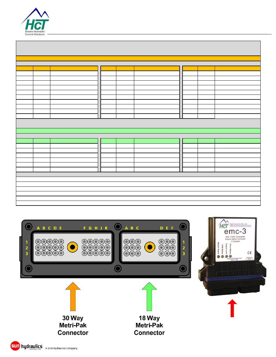
18 Pin Metri‐Pak Connector ( Male, Plug )
Notes:
emc‐3 is designed to drive up to 3 separate banks of electric fans with low currect requirement ‐ PWM command signal type inputs
emc‐3 has the capability of monitoring up to 8 individual fans operation using the digital ON/OFF inputs DIG‐1 thru DIG‐8
User system alarm, operational logic or safety inputs should use the analog inputs 1 thu 3
30 Pin Metri‐Pak Connector ( Male, Plug )
emc‐3 Connector Designation Tables
Connectors Viewed In
This Direction