Emc-3 controller module, Module configuration, User guide – rev a – High Country Tek emc-3 User Manual
Page 16
Page 16 of 39
emc-3 Controller Module
User Guide – Rev A
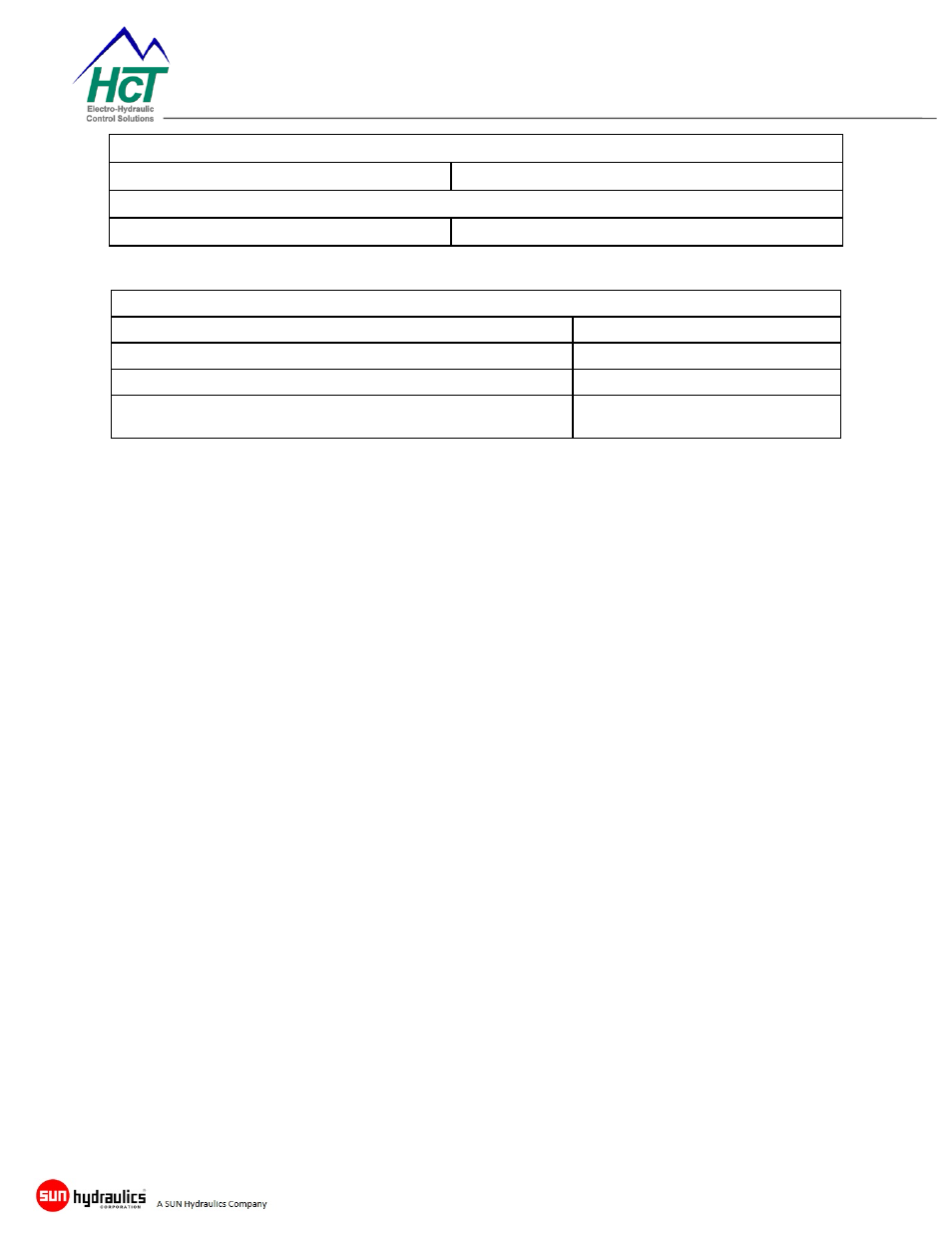
% Current O/P
LED STATE
MEANING
Off (Outputs Disabled)
GRN
(0-33%)
YEL
(34-66%)
RED
(66-100%)
Flashing
RED
PWM or High Side output Short circuit detected
Error Status
LED STATE
MEANING
Off
No errors
Flashing
YELLOW
Output Short Detected
Multi Digit Blink Code
RED
Application defined blink codes
listed above.
Module Configuration
The EMC-3 may be configured by using either the DVC PLM or from the J1939
CAN Bus using any configurable CAN application.
PLM Configuration
Open the DVC PLM and enter at least a level 1 password;
Level 1 – ycz2ee
Level 2 – a4qz6v
Level 3 – wwqelr
Using the EE-MEMORY screen, enter the desired settings and save changes.
SAE J1939 CAN Bus Configuration
The EMC-3 listens for the configuration message 18FF014Eh. When detected, it
will transmit its current configuration settings on message 18FF814Eh. Both
18FF014Eh and 18FF814Eh are multiplexed messages. Currently there are 11
separate data sets that are transmitted or received by these messages. Byte 1
bits 1 – 4 of the messages are used for multiplexing; valid multiplexing address
values are 01h through 0Bh. See below for details of each data set.
Transmitting 18FF014Eh to the EMC-3 with a particular valid multiplex address
value will cause the EMC-3 to enable and transmit the same data set on address
18FF814Eh using the same multiplexing address. To write data to the EMC-3
using a multiplexed data set, the user must set Byte 8 of 18FF014Eh to a value
of D6h to enable writing to the EE-Memory.