Chapter 3: 952 wiring connections – AMETEK 952 BlueOx LDT User Manual
Page 8
8
1080 N. Crooks Road • Clawson, MI 48017 • 800.635.0289 • 248.435.0700 • Fax 248.435.8120 • www.AMETEKAPT.com
Once the LDT has been installed, wiring
connections can be made. There are two groups of
connections that will need to be made. They are as
follows:
• Power Supply Connections
(including grounding and shielding)
• LDT Input/Output Connections
Power Supply/Ground Connections
The BlueOx standard cable is Alpha XTRA-GUARD
2 25110 SUPRASHIELD™, a multi-conductor cable
with a specially formulated polyurethane jacketing,
10 conductors of 22 ga, with an aluminum/polyester/
aluminum foil with drain wire plus an overall braid of
tinned copper shield. Cable O.D. is .30. Connector
option S, used only on the analog version, use an
industry standard 5 pin 12mm Euro style cordset
with a shield tied to the coupling nut. To reduce
electrical noise the shield must be properly used.
Connect the cable’s shield to the controller system
GND. The cable shield is not connected at the
transducer rod. Always observe proper grounding
techniques such as single point grounding and
isolating high voltage (i.e. 120/240 VAC) from low
voltage (15 - 26 VDC cables for digital LDTs) and
(13.5 - 30 VDC cables for analog LDTs).
WARNING: Do not use molded cordsets with
LED's!
It is preferable that the cable between the LDT and
the interface device be one continuous run. If you
are using a junction box, it is highly recommended
Chapter 3: 952 Wiring Connections
that the splice junction box be free of AC and/or
DC transient-producing lines. The shield should
be carried through the splice and terminated at the
interface device end.
NOTE: When grounding the LDT, a single earth
ground should be connected to the power supply
common (circuit ground). The LDT power supply
common (pin B) should be connected to the power
supply common (-) terminal. Pin C should be
connected to the power supply positive terminal (+).
The LDT cable shield should be tied to earth ground
at the power supply. The LDT analog common
should not be connected to earth ground and should
be used for connection to interface devices only. For
assistance, refer to your LDT’s wiring drawing in this
chapter.
Bipolar Wiring
If using the bipolar option, ensure that the power
supply is rated at ± 15 VDC at 100mA for each
polarity. The power supply should provide less than
1% ripple with 10% regulation.
The power supply
should be dedicated to the LDT to prevent noise
and external loads from affecting the BlueOx
performance. See Figure 3-1. For more wiring
information, see wiring diagram in this chapter. Be
sure to identify the proper version of the LDT. A
linear supply should always be used with any LDT.
NOTE: Do not use Bipolar Wiring for 952A or 952
QD. See Section 3.4 for 952A wiring details and
Section 4.6: 952 QD Wiring Connections, for wiring
details.
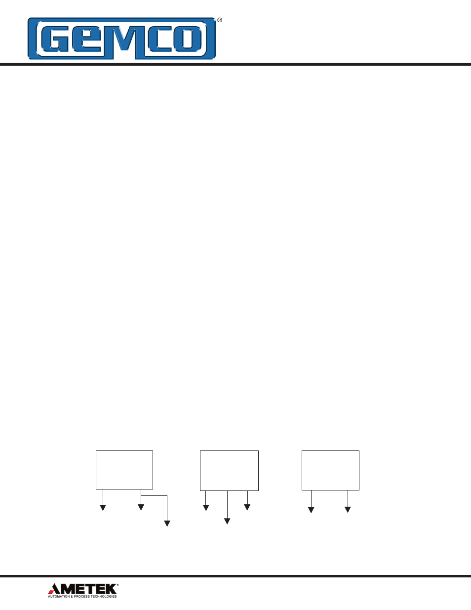
Figure 3-1: Power Supply Wiring (Unipolar/Bipolar)
Unipolar Wiring
for Digital Style LDTs
Bipolar Wiring
for Digital Style LDTs
Pin C (red) Pin B (black)
Pin J (purple)
Pin C (red)
Pin B (black)
Pin J (purple)
Pin C (red) Pin B (black)
Unipolar Wiring for Analog
Style LDTs
(10 Pin Connector E)
Single ended
power supply
+15 to +26 VDC
+ COM
Single ended
power supply
+15 to +26 VDC
+15 COM -15
Single ended
power supply
+13.5 to +30 VDC
+ COM
WARNING: Do not route the BlueOx cable near high voltage sources.