AMETEK 952 BlueOx LDT User Manual
Page 6
6
1080 N. Crooks Road • Clawson, MI 48017 • 800.635.0289 • 248.435.0700 • Fax 248.435.8120 • www.AMETEKAPT.com
2. Position the non-ferrous spacer against the
piston face, followed by the magnet, and finally
the chamfered rod bushing. (If the length of
the LDT’s rod is 60.0” or longer in length, it is
recommended that a chamfered rod bushing be
used.)
3. Insert non-ferrous screws through the
chamfered rod bushing (if used), magnet,
and non-ferrous spacer, and secure items by
tightening screws.
If the leading edge of the magnet will come
closer than 2.0” from the base of the LDT’s hex
head when the piston rod is fully retracted, it
will be necessary to counterbore the magnet
assembly into the piston rod. Both the standard
1.29” four-hole magnet assembly (part number
SD0400800) and the 1.0” magnet assembly
(part number SD0410300) are designed for
counterbored mounting applications. If it has
a 1.0” magnet assembly, a snap ring will be
needed to hold it in place.
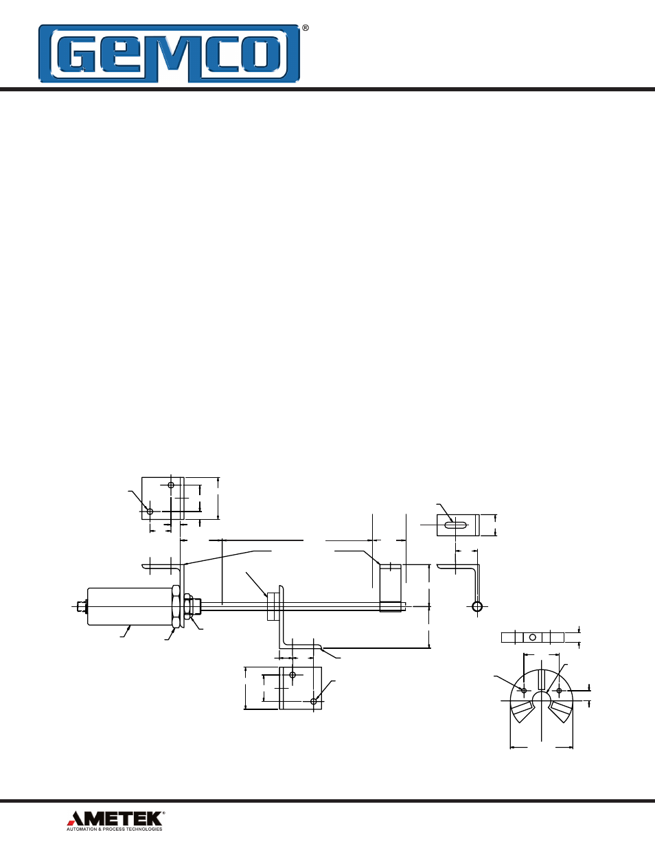
Figure 2-1: Mounting the LDT
4. Insert the LDT’s rod into the hole of the hydraulic
cylinder’s mounting bracket.
The protective Plug may need to be removed
from the hydraulic cylinder before inserting the
LDT. The end cap should contain a 3/4 - 16 UNF
- 2B threaded hole. Screw the LDT into this hole
using the threads protruding from the LDT’s hex
mounting base.
WARNING: Do not use the blue aluminum cover
of the head assembly or connector/cable nut
(either a 1 1/16" Amphenol connector or 1 3/16"
cable nut) to tighten the LDT within the bracket
(see Figure 2-1). This may damage the LDT
and will void your warranty. To tighten the LDT
within the bracket, use the 1.75" hex mounting
base on the head assembly.
At this point, the LDT should now be properly
installed inside the hydraulic cylinder. It may now
be necessary to assemble parts of the hydraulic
cylinder. For assistance in this task, refer to the
information provided by the cylinder manufacturer.
BAND
OPTIONAL
MAGNET
NULL
STROKE
DEAD
1.75 HEX
MAGNET MOUNTING
KIT (P/N 949005)
PROBE MOUNTING KIT
(P/N 949003)
2.00
2.00
3/4-16 JAM NUT
SUPPLIED W/PROBE
1.00
1.03
.28 X 1.03 SLOT
1.00
.44
1.25
2.00
.28
2 PLACES
2.00
1.25
1.00
2 PLACES
.28
.62
PROBE
3/16" X 2" X3" STAINLESS STEEL.
2. MOUNTING BRACKETS ARE MADE FROM
MOUNTING BOLTS.
1. MOUNTING KITS FURNISHED WITH
NOTES: UNLESS OTHERWISE SPECIFIED
CL
.37
2.50 REF.
.406
1.407
.75 THRU
.38
.187 THRU
(2 PLACES)
S
N
N
N
S
S
S
MAT’L.: STAINLESS STEEL.
NOTE: USE THIS MAGNET WITH ROD
SUPPORT BRACKET SD0411100