Lockouts module (3-lc) 27 – Red Lion PCU User Manual
Page 35
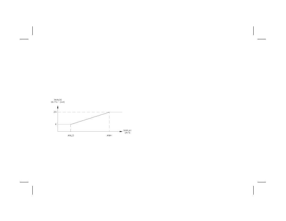
Example: Chart Record Process Display Value (0 to 10 VDC):
The process range is 300-700. Programming 300 for ANLO (0 VDC
value) and 700 for ANHI (10 VDC value) yields full scale deflection for a
chart recorder (0 to 10 VDC). The 0 to 10 VDC output is assigned to
transmit the input reading (ANAS = INP).
Example: Linear Control Output (4 to 20 mA):
A linear DC input power control unit is used for process control. An
output control deadband of ±2.0% and an output update time of 10 seconds
is desired. The following set-up values illustrate the configuration:
ANAS
=
OP
ANLO
=
0.0%
ANHI
=
100.0%
ANdb
=
2.0%
ANUt
=
10 seconds
LOCKOUTS MODULE (3-LC)
The controller can be programmed to limit operator access to various
parameters, control modes, and display contents. The configuration of the
lockouts is grouped into three sections: Lower Display Lockouts, Protected
Mode Lockouts and Hidden Mode Lockouts.
Lower Display Lockouts (SP, OP, IN-2, dEv, bdSP)
The contents of the secondary display can be changed in the normal display
mode by successively pressing the DSP button. This action scrolls through
the possible display parameters, when enabled.
The parameters can be set for one of the following:
LOC (Lockout)
–
Prevents the parameter from appearing in the
secondary display.
rEd (Read only)
–
Parameter appears, but cannot be modified.
Ent (Entry)
–
Parameter appears and can be modified.
The lower display content possibilities are:
SP
–
Setpoint Value
OP*
–
% Output Power
IN-2*
–
Second analog input (Remote setpoint)
dEv*
–
Setpoint Deviation
bdSP
–
Blank Display
If all parameters are set to lock “LOC”, the display remains on the last
parameter that was viewed.
*Note: These parameters are model specific and may not appear in the
programming sequence.
Note: If a parameter is active in the lower display and is then subsequently locked
out, press “DSP” once in the normal display mode to remove it from the display.
-27-
Figure 15, Linear DC Output