Caling, Eter, Description of operation – Red Lion PAXLSG User Manual
Page 6: Gain adjustments, Paxlsg schematic, Coarse gain select switches, Coarse and fine gain adjustments, Offset adjustments
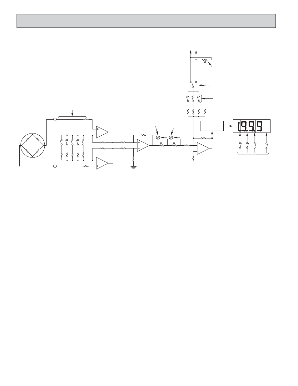
DESCRIPTION OF OPERATION
The Pax Lite Strain Gage Indicator (PAXLSG) consists of a digital voltmeter
combined with a high-gain, differential input amplifier that has provision for wide
range scaling adjustment (shown above). The unit also incorporates an excitation
power supply (5 or 10 VDC) that delivers up to 120 mA. In the simplified
schematic above, K1, K2, and K3 form a high-gain, high-stability, differential
input preamplifier with a single ended output. The gain of this preamplifier is set
up by coarse gain select switches S5 through S9. These switches can be turned on
in combination to provide discrete steps of gain-range adjustment. The output of
the preamplifier (K3 output) is applied to the summing amplifier (K4) through
coarse and fine adjustable potentiometers. These adjustable potentiometers
provide final vernier gain adjustment over a range of slightly more than 2:1. An
adjustable offset voltage signal is also added in at the input of K4 for zero-balance
or for applications where the transfer curve must be offset from zero.
GAIN ADJUSTMENTS
Gain is defined as the Units of Numerical change seen on the display per mV
(millivolt) of input signal change (disregarding display decimal points). In effect,
gain determines the slope of the transfer curve and is expressed in Units/mV.
GAIN = (Max. Num. Readout) - (Min. Num. Readout)
(Max. mV Input Sig.) - (Min. mV Input Sig.)
Note: Disregarded Decimal Points in Readout.
For example, if an PAXLSG is to display 50.0 @ 2 mV (min.) and 169.0 @
19 mV (max.), the required gain will be:
GAIN = 1690 Units - 500 Units
19 mV - 2 mV
Note: Remember, display decimal points are disregarded.
To establish this gain, the settings of the coarse gain select switches must first
be determined. These switches establish the maximum end of the 2:1 adjustment
range of the coarse and fine vernier gain adjustments.
COARSE GAIN SELECT SWITCHES
Each of the coarse gain select switches is marked with the amount of
maximum gain it will contribute when turned on. They are turned on singly or
in combination (adding up each of their gain contributions), to arrive at a
maximum gain value that is just above the desired gain value. To achieve the
desired gain of 70 Units/mV in the example just given, the following switches
would be turned on:
S6 (Gain 50) + S7 (Gain 16) + S8 (Gain 6.6) = 72.6 Units/mV
With these switches ON, the coarse and fine vernier adjustments cover a gain
range from about 36 Units/mV (½ of max.) to 72.6 Units/mV. The required gain
of 70 Units/mV falls within this adjustable range.
COARSE AND FINE GAIN ADJUSTMENTS
Once the gain select switches have been set, the final gain calibration is made
with the Coarse and Fine Gain adjustments. Both of these adjustments are
15-Turn, screwdriver adjustable potentiometers that increase gain with
clockwise rotation. The Coarse adjustment has a 2:1 range. The Fine adjustment
has a range of 5-10% (depending on the setting of the Coarse adjustment). Both
pots are located at the rear of the meter.
OFFSET ADJUSTMENTS
Offset adjustments move the transfer curve up-and-down along the vertical axis
without changing the slope (Gain). They are used to “balance” the output of
transducers or to intentionally introduce an offset, such as tare-load compensation.
The Fine Offset Adjustment is a 15-turn screwdriver adjustable potentiometer,
located at the rear of the meter. It has a range of ±125 Numerical Units of offset
which is sufficient for balancing the output of most transducers.
The Coarse Offset Switches (S2, 3, and 4) can be used to add additional steps
of offset. Like the coarse gain select switches, the offset switches are marked
with the approximate value of offset contributed by each switch, and they can
be turned on in combinations with each switch, contributing its value to the
total. Switch S1 selects the polarity of the offset signal and can be set to either
add or subtract the offset contribution of the switches. The maximum offset that
can be obtained with all switches ON and the Fine Offset at its maximum is
±1000, which is one half of the full scale readout.
6
= 70 Units/mV
K1
.77K
S1
68.1K
2.2K
7.15K
22.6K
(+)
(-)
50K
S3
S2
S1
DIGITAL DISPLAY
S8
S7
S6
S5
S9
140 U/MV
50 U/MV
16 U/MV
6.6 U/MV
3.3 U/MV
K3
K2
30K
30K
30K
30K
5
6
30K
30K
CW
5K
CW
45K
K4
30K
100K
S3
500
S2
200K
400K
250
125
S4
800K
DECIMAL POINT / BACKLIGHT
SWITCHES
DIGITAL VOLT-
METER & DISPLAY
DRIVER CIRCUIT
COARSE OFFSET
SELECT SWS.
FINE OFFSET
ADJ.
+V -V
+SIG.
-SIG.
-EXC.
+EXC.
(+)SIG.
(-)SIG.
GAIN COARSE
SELECT SWITCHES
COARSE GAIN
ADJ.
FINE GAIN ADJ.
+/-OFFSET
SELECT
5K
5K
S4
STRAIN GAGE
TRANSDUCER
5K
V
PAXLSG SCHEMATIC
4.0 S
CALING
THE
M
ETER