2 module 2 - s, 0 hi-t, No lo-en – Red Lion CUB5V User Manual
Page 8: No fcs, 0 lo-t, No usrin, Dsp u-asn, No hi-en, 48 code, 66 code
Entering Code 66 will overwrite all user settings with
the factory settings. The meter will display
rESEt
and then
return to
CodE 00
. Press the
SEL button to exit the module.
Entering Code 50 will display the version (x.x) of the
meter. The display then returns to
CodE 00
. Press the
SEL
button to exit the module.
8
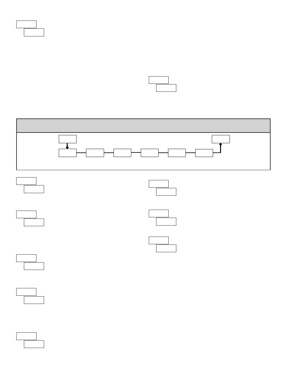
6.2 Module 2 - S
econdary
f
unction
p
araMeterS
(
2-SEC
)
SEL
Max Capture
Delay Time
Max Display
Enable
Min Display
Enable
Access Code
For Service
Operations
Min Capture
Delay TIme
Factory
Service
Operations
2-SEC
HI-En
HI-t
LO-En
LO-t
FCS
CodE
Pro
PARAMETER MENU
MIN DISPLAY ENABLE
USER INPUT ASSIGNMENT
Select the value(s) to which the User Input Function is assigned. The User
Input Assignment only applies if a selection of reset, display hold, or print and
reset is selected in the User Input Function menu.
MODE
DISPLAY
No Function
NO
DESCRIPTION
User Input disabled.
Program Mode Lock-out
P-Loc
Zero Input
(Edge triggered)
ZErO
Zero the Input Display value causing
Display Reading to be Offset.
COLOr
d-SEL
d-LEV
d-HLd
rESEt
Resets the assigned value(s) to the
current input value.
HI-LO
HI
dSP
LO
See Programming Mode Access chart
(Module 3).
YES
NO
MODE
DESCRIPTION
DISPLAY
Setpoint 1 and 2 Reset
Setpoint 1 Reset
Setpoint 2 Reset
Print and Reset
Reset both setpoint 1 and 2 outputs.
Resets setpoint 1 output.
Resets setpoint 2 output.
Same as Print Request followed by a
momentary reset of the assigned value(s).
rSt12
rSt-1
rSt-2
P-r5t
Print Request
Serial transmit of the active parameters
selected in the Print Options menu
(Module 5).
2.0
HI-t
NO
LO-En
NO
FCS
MAX CAPTURE DELAY TIME
When the Input Display is above the present MAX value for the entered
delay time, the meter will capture that display value as the new MAX reading.
A delay time helps to avoid false captures of sudden short spikes.
2.0
LO-t
MIN CAPTURE DELAY TIME
When the Input Display is below the present MIN value for the entered delay
time, the meter will capture that display value as the new MIN reading. A delay
time helps to avoid false captures of sudden short spikes.
0.0
to
999.9
seconds
USER INPUT FUNCTION
NO
USrIN
dSP
U-ASN
NO
HI-En
MAX DISPLAY ENABLE
0.0
to
999.9
seconds
Select
yES
to perform either of the Factory Service Operations shown below.
FACTORY SERVICE OPERATIONS
yES
NO
YES
NO
Enables the Maximum Display Capture capability.
Enables the Minimum Display Capture capability.
The CUB5V uses stored voltage calibration values to
provide accurate voltage measurements. Over time, the
electrical characteristics of the components inside the meter
will slowly change, with the result that the stored calibration
values no longer accurately define the input circuit. For most applications,
recalibration every 1 to 2 years should be sufficient.
Calibration of the CUB5V involves an input voltage calibration, which
should only be performed by individuals experienced in calibrating electronic
equipment. Allow a 30 minute warm up before performing any calibration
related procedures. The following procedures should be performed at an
ambient temperature of 15 to 35°C (59 to 95°F).
CAUTION: The accuracy of the calibration equipment will directly affect the
accuracy of the CUB5V.
Voltage Calibration
1. Connect a precision DC voltage source with an accuracy of 0.01% or better
to the INP+ (positive) and COMM (negative) terminals of the CUB5V. Set
the output of the voltage source to zero.
2. With the display at
CodE 48
, press and hold the
SEL
button for 2 seconds. Unit
will display
CAL NO
.
3. Press the
RST
button to select the range to be calibrated.
4. Press the
SEL
button. Display reads
0.0v
.
5. With the voltage source set to zero (or a dead short applied to the input), press
SEL
. Display reads
CALC
for about 8 seconds.
6. When the display reads the selected range, apply full-scale input signal for
the range. (Note: For 200V range, apply 100V as indicated on the display.)
Press
SEL
. Display reads
CALC
for about 8 seconds.
7. Repeat steps 3 through 6 for each input range to be calibrated. When display
reads
CAL NO
, press the
SEL
button to exit calibration.
CALIBRATION
48
CodE
66
CodE
50
CodE
RESTORE FACTORY DEFAULT SETTINGS
VIEW VERSION DISPLAY
Backlight Color
(Edge Triggered)
Display Select
(Edge Triggered)
Display Intensity Level
(Edge Triggered)
Display Hold
Reset (Edge triggered)
Change backlight color with each
activation (backlight version only).
Advance once for each activation.
Increase intensity one level for each
activation (backlight version only).
Holds the assigned display, but all other
meter functions continue as long as
activated (maintained action).