L.s. input; logic versions (10 khz, Installation environment, Installation – Red Lion CUB7 User Manual
Page 4
4
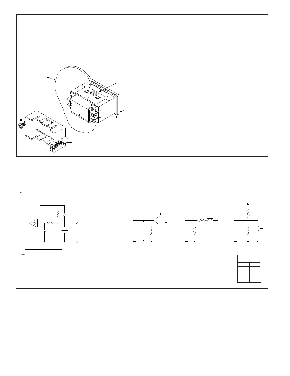
The “LS.” Input allows the CUB7P to operate at speeds up to 10 KHz when
driven by bi-polar outputs or external circuits having an output impedance of
3.3 K
or less. Input drive voltage must be limited to 3 V maximum to avoid
damage to the counter. CMOS and TTL Logic outputs can be loaded with a
resistor (R
L
) to limit drive voltage, or a voltage divider can be used as shown
for the PNP O.C. Transistor output.
L.S. INPUT; LOGIC VERSIONS (10 KHz
MAX
.)
+3V
MICRO
CHIP
COM
0.0033µf
10K
470K
BATT.
3.0V
L.S.
COM/NEUTRAL
C
3.0 V
MAX.
R
L
SEE
TEXT
L.S.
COM
+5 VDC
COM
3.3 K
L.S.
R
+V
COM
L.S.
3.3 K
R
+V
TTL OR CMOS
PNP O.C. TRANSISTOR
NPN O.C.
OUTPUT
OR BI-POLAR OUTPUT
TRANSISTOR
FIG 1
FIG 2
FIG 3
R values for
Fig 2 & 3
+V
R
+5 V 2.2 K
+12 V 10 K
+18 V 16 K
+24 V 24 K
INSTALLATION ENVIRONMENT
The unit should be installed in a location that does not exceed the maximum
operating temperature and provides good air circulation. Placing the unit near
devices that generate excessive heat should be avoided.
The bezel should be cleaned only with a soft cloth and neutral soap product.
Do NOT use solvents.
Continuous exposure to direct sunlight may accelerate the aging process of
the bezel.
Do not use tools of any kind (screwdrivers, pens, pencils, etc.) to operate
the push buttons of the unit.
INSTALLATION
The CUB7P meets NEMA 4X/IP65 requirements for indoor use when
properly installed. The units are intended to be mounted into an enclosed
panel. The viewing window and reset button are factory sealed for a washdown
environment. A sponge rubber gasket and mounting clip are provided for
installing the unit in the panel cut-out.
The following procedure assures proper installation:
1. Cut panel opening to specified dimensions. Remove burrs and clean around
panel opening.
2. Carefully remove and discard the center section of the gasket.
3. Slide the panel gasket over the rear of the counter body to the back of the
bezel. Install CUB7P unit through the panel cut-out.
4. Insert the mounting screws onto both sides of mounting clip. Tip of screw
should NOT project from hole in mounting clip.
5. Slide the mounting clip over the rear of the unit until the clip is against the
back of the panel. The mounting clip has latching features which engage
into mating features on the CUB7P housing.
6. Note: It is necessary to hold the unit in place when sliding mounting clip
into position.
7. Alternately tighten each screw to ensure uniform gasket pressure.
Visually inspect the front panel gasket. The gasket should be compressed to
about 75 to 80% of its original thickness. If not, gradually turn mounting
screws to further compress gasket.
8. If the gasket is not adequately compressed and the mounting screws can no
longer be turned, loosen mounting screws, and check that the mounting clip
is latched as close as possible to the panel.
9. Repeat from step #5 for tightening mounting screws.
HS-6
+V-2
LS-4
3-RST EN
1-COM
5-RST
LATCHING
FEATURE
BEZEL
GASKET
0.062"
(1.57 mm)
THICK
EXISTING
PANEL
0.05" to 0.20"
(1.3 to 5.1 mm)
THICK
MOUNTING
SCREW
MOUNTING
CLIP