Ethernet communications, Rs232 ports, G310 port pin outs – Red Lion G310 10" TFT Color Touch Panel User Manual
Page 4: G3 rs232 to a pc
4
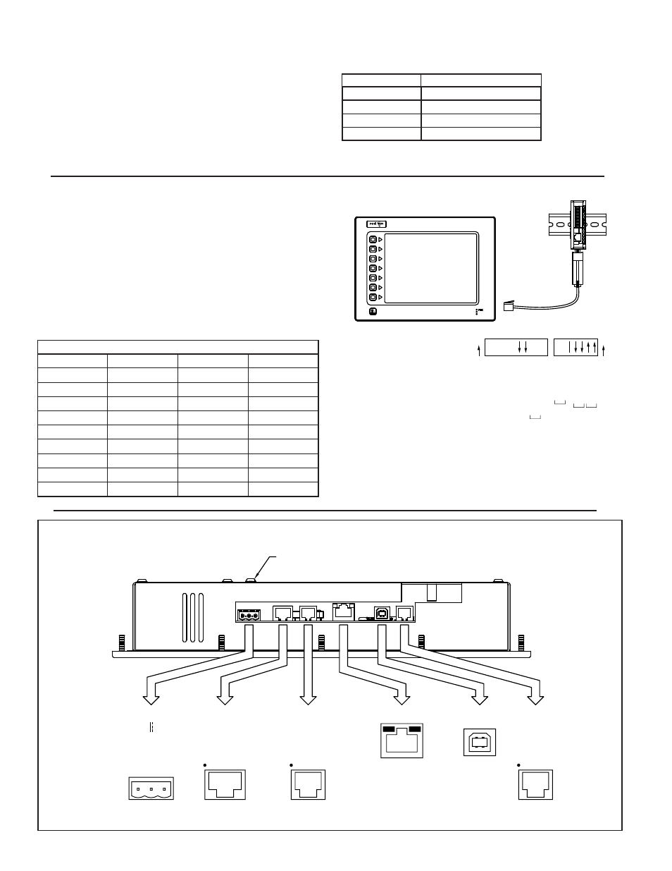
ETHERNET COMMUNICATIONS
Ethernet communications can be established at either 10 BASE-T or 100
BASE-TX. The G310 unit’s RJ45 jack is wired as a NIC (Network Interface
Card). For example, when wiring to a hub or switch use a straight-through cable,
but when connecting to another NIC use a crossover cable.
RS232 PORTS
The G310 has two RS232 ports. There is the PGM port and the COMMS port.
Although only one of these ports can be used for programming, both ports can
be used for communications with a PLC.
The RS232 PGM port can be used for either master or slave protocols with
any G310 configuration.
Examples of RS232 communications could involve another Red Lion product
or a PC. By using a cable with RJ12 ends on it, and a twist in the cable, RS232
communications with another G3 product or the Modular Controller can be
established. Red Lion part numbers for cables with a twist in them are
CBLPROG0
1
, CBLRLC01
2
, or CBLRC02
3
.
The Ethernet connector contains two LEDs. A yellow LED in the upper right,
and a bi-color green/amber LED in the upper left. The LEDs represent the
following statuses.
The Crimson manual contains additional information on Ethernet
communications.
N/C
COMMON
24V 20%
Tx
RTS (PIN 6)
Rx
COMM
TxA
COMM
RxB
TxEN
TxB
RxA
TxA (PIN 8)
CTS (PIN 1)
COMM
Rx
COMM
Tx
COMM
TxB (PIN 1)
RTS (PIN 6)
CTS (PIN 1)
POWER
CONNECTOR
1
PORT
PORT
COMMS
2
3
RS485
COMMS
RS232
(NIC)
ETHERNET
PGM PORT
TYPE B
USB
RS232
PROTECTIVE EARTH GROUND
+ -
G310 PORT PIN OUTS
Connections
G3: RJ12
Name
PC: DB9
Name
4
COMM
1
DCD
5
Tx
2
Rx
2
Rx
3
Tx
N/C
4
DTR
3
COM
5
GND
N/C
6
DSR
1
CTS
7
RTS
6
RTS
8
CTS
N/C
9
RI
OFF 4 WIRE/ ON 2 WIRE
OFF 4 WIRE/ ON 2 WIRE
*
*
*
*
*
*
* * *
*
9
PULL UP
PULL DOWN
115200 BAUD
57600 BAUD
38400 BAUD
19200 BAUD
9600 BAUD
2
1
5
3
4
7
8
6
OFF DCE/ ON DTE
OFF DCE/ ON DTE
OFF DTE/ ON DCE
OFF 422/ ON 485
OFF 422/ ON 485
OFF DTE/ ON DCE
120
Ω
TERMINATION
5
NC
10
1
3
2
4
6
7
ON
ON
CBLPROG0
ICM5
CONNECTING A G310 OPERATOR
INTERFACE TO AN ICM5
*
Application Dependent
ICM5 DIP Switch Settings
1
CBLPROG0 can also be used to communicate with either a PC or an ICM5.
2
DB9 adapter not included, 1 foot long.
3
DB9 adapter not included, 10 feet long.
LED COLOR
DESCRIPTION
YELLOW solid
Link established.
YELLOW flashing
Data being transferred.
GREEN
10 BASE-T Communications
AMBER
100 BASE-TX Communications
G3 RS232 to a PC