Vaisala WMT700 User Manual
Page 31
Chapter 3 _________________________________________________________ Retrofit Installation
VAISALA _______________________________________________________________________ 29
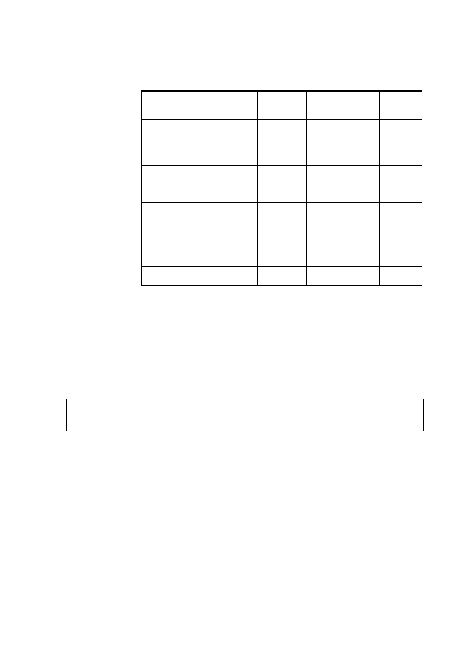
Table 7
Pin-Outs for WS425 Analog Voltage Output Adapter
Cable
WMT700
Connector
Pin
WMT700 Signal
Description
WS425
Connector
Pin
WS425 Signal
Description
WS425
Wire
Color
1 Operating
Power
Supply
11 +12
VDC Brown
2 Analog
Output
AOUT2, Wind
Direction
13 WD
Vout Grey
5 Heater
Power
Supply
16 +36
VDC Grey/Pink
7 Heater
Power
Supply Ground
3 GND
Green
11 Operating
Power
Supply Ground
1 GND
Black
12 Analog
Output
Ground
8 GND
Yellow
13 Analog
Output
AOUT1, Wind
Speed
15 WS
Vout Violet
17 Reference
Input
for AOUT2
12
WD Vref in
White
Differences between WMT700 and WS425
Analog Output Signals
WMT700 pin connections differ from the connections of WS425 in that
wind speed signal output, both voltage and frequency signals, appears on
WMT700 pin 13.
NOTE
WMT700 analog outputs must be configured according to the appropriate
analog output mode, which is either voltage, frequency, or potentiometer.
Table 8 on page 30 lists the analog output connections for WMT700 and
WS425 connector pins.