DAVIS Vantage Pro ISS, 2002 & earlier User Manual
U i t e
Product # 6150, 6150C, 6160, 6160C
I
N T E G R A T E D
S
E N S O R
S
U I T E
I
N S T A L L A T I O N
M
A N U A L
For Vantage Pro
TM
or Vantage Pro Plus
TM
The
Integrated Sensor Suite (ISS)
collects several types of weather readings
for display at your Vantage Pro
TM
console. The data is sent to the console either
through a cable or by wireless transmission, depending on the version.
With Wireless Vantage Pro
TM
, the Integrated Sensor Suite (ISS) can be used as
one of eight sensor stations transmitting to your console/receiver(s). See
“Additional Mounting Options” and “Appendix A: Wireless Transmitter IDs”.
The Integrated Sensor Suite for Vantage Pro
TM
measures weather conditions:
✦
Wind Speed
✦
Wind Direction
✦
Rainfall
✦
Outside Temperature
✦
Outside Humidity
The Integrated Sensor Suite for Vantage Pro
Plus
TM
also measures:
✦
Ultraviolet Radiation (UV)
✦
Solar Radiation
Note:
To upgrade a Vantage Pro system to Vantage Pro Plus, see “Appendix B: Optional Accessories”.
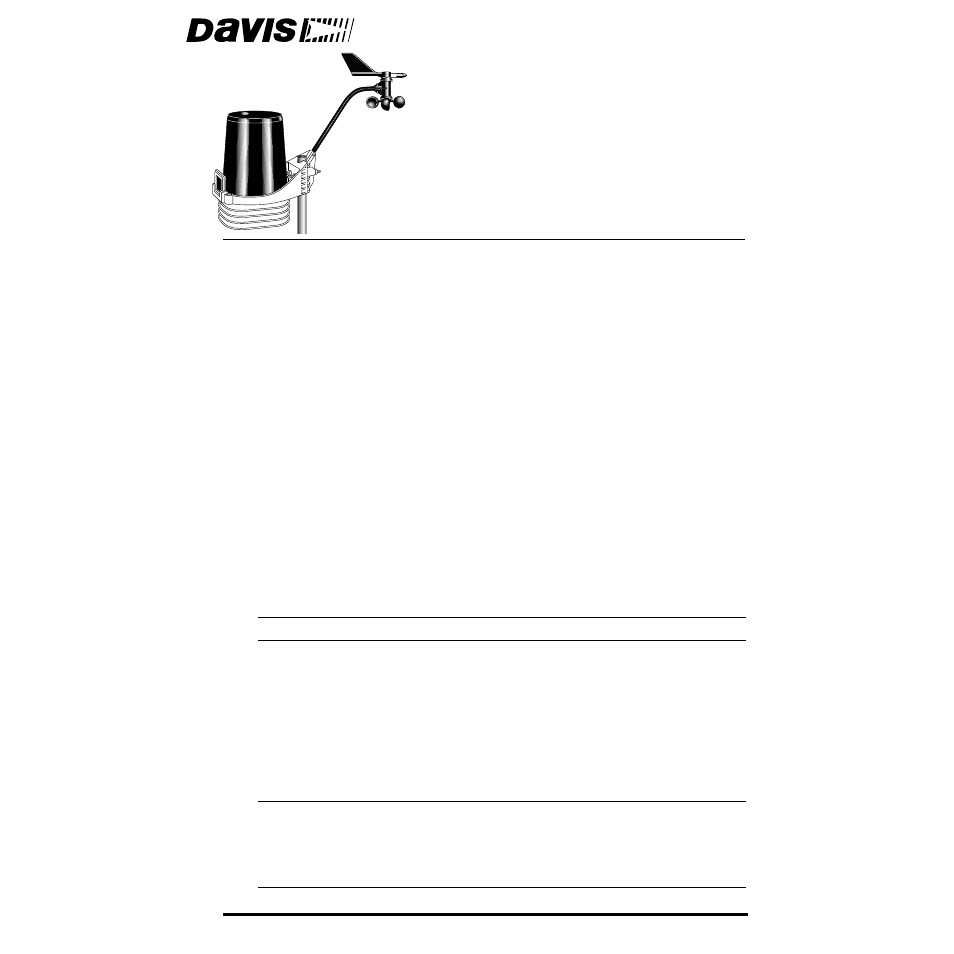
For mounting purposes,
the Integrated Sensor Suite (ISS) consists of two sides:
the anemometer and the rain collector side.
The rain collector side is a white plastic shelf with the black rain collector cone
on top and the white radiation shield below.
The two sides can be mounted either
together
on a single pole (see illustration at
the top of this page), or
separately
. The anemometer has 40' (12 m) of cable.
Note:
When both sides of the ISS are mounted together with the anemometer arm pointing north, the
solar panel on the rain collector side is facing south. In the Northern Hemisphere, this positions
the solar panel for optimal exposure to the sun. (In the Southern Hemisphere, you will need
to position the solar panel facing north for optimal sun exposure. When mounting both sides
together, this means pointing the anemometer arm south and re-orienting the wind vane.)
Document Outline
- Integrated Sensor Suite
- The Integrated Sensor Suite (ISS) collects several types of weather readings for display at your ...
- Components
- Table of Contents
- Tools for Setup
- Preparing the Anemometer
- Attaching Anemometer Arm to Base
- Attaching Wind Cups to Anemometer Arm
- 1. Slide the black plastic drip ring onto the anemometer head. Gently push the drip ring up until...
- 2. Make sure the lower edge of the drip ring is aligned with the lower edge of the anemometer head.
- 3. Push the wind cups up onto the stainless steel shaft that is protruding downward.
- 4. Slide the wind cups up the shaft as far as possible.
- 5. Use the Allen wrench provided to tighten the set screw on the side of the wind cups.
- 6. Spin the wind cups.
- Attaching Wind Cups to Anemometer Arm
- Wind Vane Must Be Correctly Oriented
- Ensure correct orientation of the wind vane in one of two ways:
- 1. Mount the anemometer so that the arm points north.
- Disassembling the Radiation Shield
- Removing Radiation Shield Plates
- 1. Turn the rain collector side of the ISS upside down. Locate three wing nuts on the underside o...
- 2. Remove the wing nuts, lock washers and flat washers.
- 3. Remove the first three plates of the radiation shield.
- 4. Verify that the rain sensor cable is plugged into the receptacle labeled “RAIN” on the SIM.
- 5. If you have a Vantage Pro Plus, verify that the UV and solar radiation sensors are plugged int...
- Sensor Interface Module (SIM)
- Connecting Anemometer to SIM
- (Wireless Vantage Pro instructions continue on page 12.)
- Cabled Version: Powering the ISS and Testing Communication with the Console
- Wireless Version: Powering the ISS and Testing Communication with the Console
- DIP Switches in Top-right Corner of SIM (Illustration has been enlarged for clarity)
- 1. You changed the transmitter ID on the ISS but didn’t change it at the console/receiver.
- Reassembling the Radiation Shield
- Preparing the Rain Collector
- See the illustration on the following page.
- 1. Remove the rain collector cone from its base by rotating the cone counter-clockwise until its ...
- 2. Carefully cut and remove the plastic cable tie (usually black in color) that holds the two-sid...
- 3. On your console screen, look for DAILY RAIN display.
- 4. While watching the daily rain display, slowly tip the bucket mechanism until it drops to oppos...
- 5. You can put the rain collector cone back on temporarily, but you will need to remove it again ...
- Choosing a Location to Mount the Integrated Sensor Suite
- Mounting the Integrated Sensor Suite
- Mounting on a Post
- Mounting on a Pole
- Start by mounting the rain collector side
- 1. Place the U-bolt for the anemometer around the pole so that its round end will fit in the top ...
- 1. The two ends of the anemometer’s U-bolt should now be pointing away from the mounted rain coll...
- 1. While holding the mounting base against the pole, place the two ends of a U-bolt around the po...
- 2. Slide the metal backing plate over the bolt ends as they stick out toward the rain collector c...
- 3. Using an adjustable wrench or 7/16" wrench, tighten the nuts.
- 4. Re-attach the rain collector cone.
- 5. Place the debris screen (shown in the illustration on page 2) inside the cone, “feet- down” ov...
- Mounting Anemometer on a Pole by Itself
- 1. While holding the mounting base against the pole, place a U-bolt around the pole and through t...
- 1. With a 3/16" (5 mm) drill bit, drill two holes approximately 2-1/8" (54 mm) apart. Use a carpe...
- 2. Insert the 1/4" x 3" lag screws through the metal backing plate and the holes in the mounting ...
- 3. Using an adjustable wrench or 7/16" wrench, tighten the lag screws.
- 4. Re-attach the rain collector cone.
- 5. Place the debris screen (shown in the illustration on page 2) inside the cone, “feet- down” ov...
- Mounting Anemometer on a Vertical Surface
- 1. With a 3/16" (5 mm) drill bit, drill two holes approximately 2-1/8" (54 mm) apart. Use a carpe...
- 1. Press the WIND key so the graph icon appears underneath “Wind” in top-left corner.
- A Note on Securing Cables
- Additional Mounting Options
- Maintenance
- Troubleshooting
- Contacting Davis Instruments
- Weather Variable Update Intervals
- Specifications for Cabled Version
- Specifications for Wireless Version
- Appendix A: Wireless Transmitter IDs
- DIP Switches in Top-right Corner of SIM (Illustration has been enlarged for clarity)
- ID Code
- Switch 1
- Switch 2
- Switch 3
- Using Multiple Transmitting Stations with Wireless Vantage Pro
- Appendix B: Optional Accessories
- Appendix C: Re-orienting the Wind Vane
- Wind Direction Chart
- Placing Vane onto Shaft
- Securing Wind Vane