Preparing the temperature station, Setting the transmitter id – DAVIS Wireless Temperature Station (6372) Installation Manual User Manual
Page 3
3
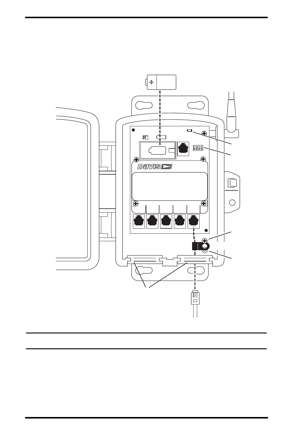
Preparing the Temperature Station
The illustration below shows the Sensor Interface Module, or “SIM”,
inside the shelter.
Insert the 3-volt lithium battery into the battery holder, matching the “+”
sign on the battery with the “+” sign on the SIM.
3-Volt
Lithium Battery
DIP Switches
Cable Clamp
Mount
Temperature Probe
Cable
Square Black Grommets
SENSOR
SENSOR
INTERFACE
INTERFACE
MODULE
MODULE
UV
UV
SUN
SUN
RAIN
RAIN
WIND
WIND
TEMP
TEMP
HUM
HUM
+
-
Cable Clamp
Test LED
Cable Clamp
Screw
Sensor Interface Module on Wireless Temperature Station
Note:
Note the location of the DIP switches. You will work with them during the next installation step.
The Temperature Probe Cable is installed and mounted with the cable clamp at the factory.
Setting the Transmitter ID
Each wireless transmitting station must be set to one of eight transmitter
IDs. DIP switches #1, 2 and 3 on the SIM allow you to control the ID —
the “channel” the station transmits on. (DIP switch #4 is used for
transmission testing, not for transmitter ID.)
- Envoy8X Getting Started Guide (16 pages)
- Vantage Pro2 Long Range Repeater Installation Addendum (16 pages)
- Solar Power Kit For Vantage Weather Stations and Envoy8X (8 pages)
- Energy EnviroMonitor: Console (63 pages)
- EZ-Mount Installation (16 pages)
- Gro/Energy/Health Installation (24 pages)
- GroWeather Console (65 pages)
- GroWeather/EnviroMonitor: Systems Installation (24 pages)
- Health EnviroMonitor: Console (60 pages)
- Anemometer (7911, 7914) (8 pages)
- Rain Collector II for GroWeather, EnviroMonitor, Weather Monitor and Wizard (16 pages)
- Sensor - UV for GroWeather or EnviroMonitor (16 pages)
- Solar Radiation Sensor for GroWeather and EnviroMonitor (16 pages)
- Temperatur/Humidity Sensor for GroWeather, EnviroMonitor, & Weather Monitor (12 pages)
- Temperature Sensor/Probe for GroWeather, EnviroMon., Weather Monitor/Wizard (4 pages)
- GroWeatherLink Software (108 pages)
- GroWeatherLink/ET Data Logger (2 pages)
- Short-Range Modem Pair: Perception, GroWeather, EnviroMon., Monitor, Wizard (8 pages)
- Alarm Output Module (16 pages)
- Cable Coupler Kit (4 pages)
- Cable Crimp-Type Splice Connector (4 pages)
- Complete System Shelter (12 pages)
- Fan-Aspirated Radiation Shield (24 pages)
- Grounding Kit (4 pages)
- Interface Cable Adapter Module (8 pages)
- Mounting Pole Kit Installation (4 pages)
- Mounting Tripod Kit (8 pages)
- Multi-purpose Shelter (12 pages)
- Radiation Shield (7714) (16 pages)
- Radio Surge Protector (4 pages)
- Rain Collector Heater (12 pages)
- Rain Collector Shelf: GroWeather, EnviroMonitor, Weather Monitor & Wizard (8 pages)
- Second Solar Panel for EZ-Mount Solar Power Kit (4 pages)
- Sensor Mounting Arm for GroWeather, EnviroMonitor, Weather Monitor & Wizard (16 pages)
- Sensor Tilting Bracket for GroWeather or EnviroMonitor (8 pages)
- Shelter Heaters (12 pages)
- Solar Power Kit for Non-Vantage Pro Stations (16 pages)
- Surge Protector (2 pages)
- Surge Protector Shelter - Large (8 pages)
- Surge Protector Shelter - Small (4 pages)
- Terminal Box for sensors/interface module, communication lines: GroWeather (8 pages)
- WeatherLink for Windows 4.0 (116 pages)
- WeatherLink Getting Started Guide (20 pages)
- WeatherLink Mac OS X Getting Started Guide (16 pages)