10 sensor connection and calibration – Boonton 4530 Peak Power Meter User Manual User Manual
Page 38
3-16
Chapter 3
Boonton Electronics
Operation
4530 Series RF Power Meter
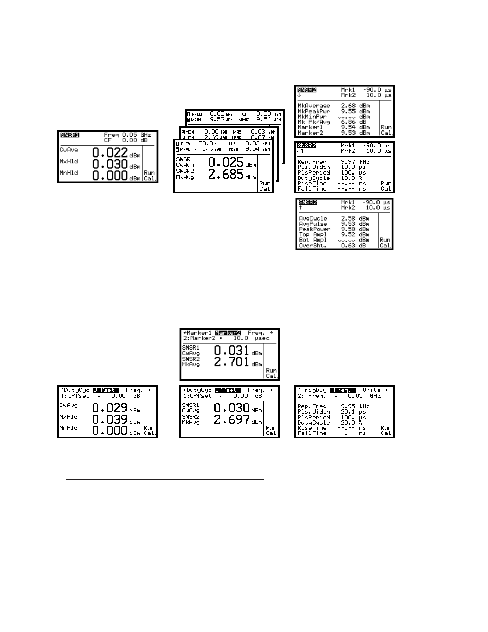
Channel 1
Both Channels
Channel 2
CW Sensor
Peak Sensor (Pulse Mode)
Figure 3-17. Text Mixed Mode Measurement Displays
Channel 1
Both Channels
Channel 2
CW Sensor
Peak Sensor (Pulse Mode)
Figure 3-18. Text Mixed Mode Edit Displays
3.10 SENSOR CONNECTION AND CALIBRATION
RF Power Sensors or Voltage Probes are used to sense the high-frequency RF signal and convert it to a voltage that is
proportional to the input amplitude. A number of different sensor types are available depending on the frequency,
power level, modulation and impedance of the signal to be measured. These sensors generally consist of an input
connector appropriate for the signal’s frequency band, and internal RF detection and processing circuitry, as well as a
non-volatile EEPROM memory that stores sensor characteristics and calibration information. A power sensor cable
routes the sensor’s output signal to the sensor input connectors on the 4530’s front or rear panel. In CW sensors, the
EEPROM is located at the instrument end of the sensor cable rather than in the sensor itself.