Operation, 1 operating controls, indicators and connections – Boonton 4530 Peak Power Meter User Manual User Manual
Page 23
3-1
Boonton Electronics
Chapter 3
4530 Series RF Power Meter
Operation
3.
OPERATION
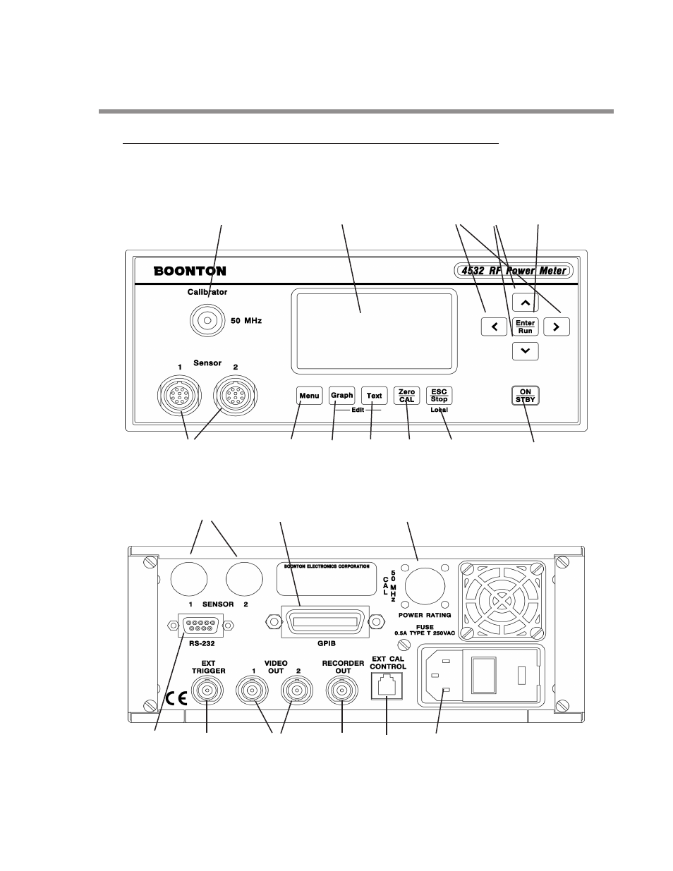
3.1 OPERATING CONTROLS, INDICATORS AND CONNECTIONS
Controls, indicators and connectors for the 4530 Series RF Power Meter are shown in figures 3-1 and 3-2. The front
panel is illustrated in figure 3-1 and the rear panel in figure 3-2.
1
2
3
4
5
12
11
10
9
8
7
6
Figure 3-1. 4530 Series, Front Panel
12
13
1
18
17
16
15
14
19
Figure 3-2. 4530 Series, Rear Panel