HP 3PAR System Reporter Software User Manual
Page 185
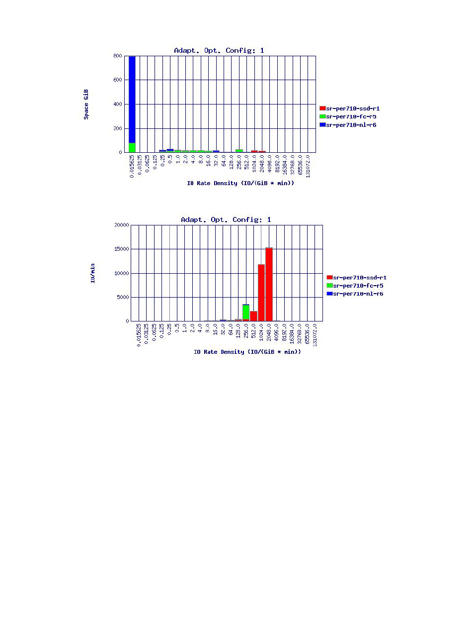
Figure 61 Region IO Density Showing Total Space
Figure 62 Region IO Density Showing Total IO Access
Each region is put into the appropriate histogram bucket on the X-axis based on its IO access rate
during the specified time period. The Y-axis (value) for the first chart is the total space for the regions
in the histogram bucket, and the Y-axis (value) for the second chart is the total IO accesses/min
for the regions in the histogram bucket. The three CPGs corresponding to the three tiers on an
Adaptive Optimization configuration are shown with different colors on the same chart, in this
case regions in green are tier 0, regions in blue are tier 1 and regions in blue are tier 2.
You can see from first chart (
) that most of the space is used by tier 2 (blue)
for regions that have a very small access rate. You can also see from the second chart (
) that most of the IO accesses are handled by the regions in tier 0 (red) even though the
first chart shows that these regions occupy very little space. This case illustrates Adaptive
Optimization working very well: the fastest tier handles most of the IO accesses even though it
uses very little space, and conversely most of the space is on the slower tier even though it does
very little IO. The region IO density report can also be useful to see if Adaptive Optimization will
be useful for the space in a CPG.
shows the Region IO density report for a CPG without Adaptive Optimization.
The charts shown are very similar to the charts in
and
except that there is only one tier (CPG).
Adaptive Optimization Reports 185