System maintenance switch, Drive bay numbering – HP ProLiant SL210t Gen8 Server User Manual
Page 14
Component identification 14
For more information, see the HP website
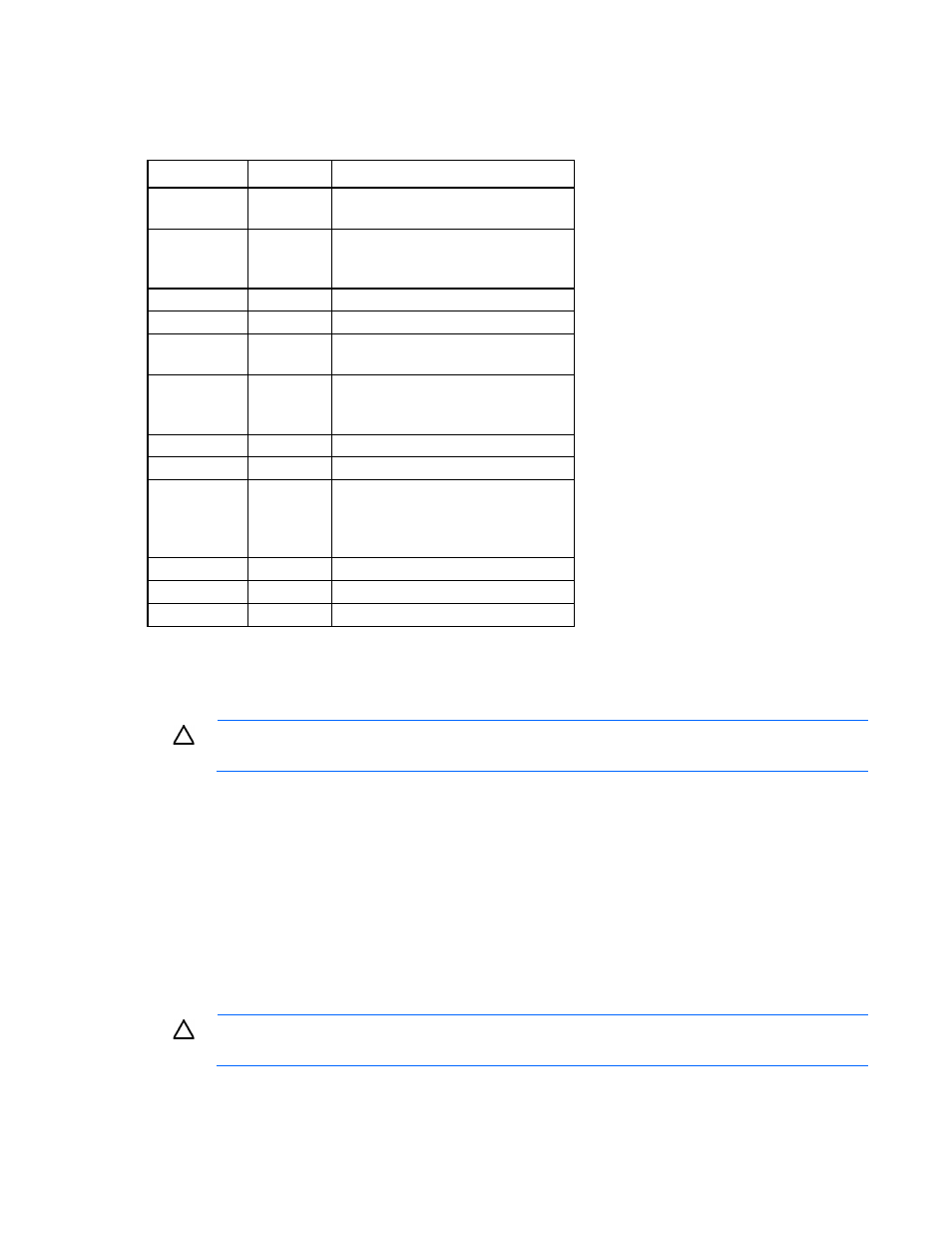
System maintenance switch
Position
Default
Function
S1
Off
Off = iLO security is enabled.
On = iLO security is disabled.
S2
Off
Off = System configuration can be
changed.
On = System configuration is locked.
S3
Off
Reserved
S4
Off
Reserved
S5
Off
Off = Power-on password is enabled.
On = Power-on password is disabled.
S6
Off
Off = No function
On = ROM reads system configuration
as invalid.
S7
—
Reserved
S8
—
Reserved
S9
—
Off = PCIe 64-bit BAR function (large
BAR) is disabled.
On = PCIe 64-bit BAR function (large
BAR) is enabled.
S10
—
Reserved
S11
—
Reserved
S12
—
Reserved
To access the redundant ROM, set S1, S5, and S6 to on.
When the system maintenance switch position 6 is set to the On position, the system is prepared to erase all
system configuration settings from both CMOS and NVRAM.
CAUTION:
Clearing CMOS and/or NVRAM deletes configuration information. Be sure to
properly configure the server or data loss could occur.
Drive bay numbering
•
Drive bay numbering for four 1U nodes
In an 8-drive bay LFF drive configuration, drives are numbered from top to bottom in each box.
o
Drives in the first box correspond to node 1.
o
Drives in the second box correspond to node 2.
o
Drives in the third box correspond to node 3.
o
Drives in the fourth box correspond to node 4.
CAUTION:
To prevent improper cooling and thermal damage, do not operate the chassis unless
all bays are populated with a component or a blank.