Installing the eight-bay sff drive cage (bay 3) – HP ProLiant ML370 G6 Server User Manual
Page 61
Hardware options installation 61
12.
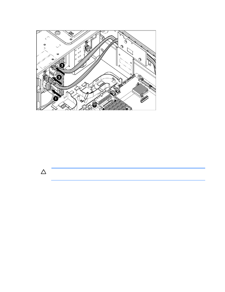
Route and connect the drive cage bay 2 power cable (BP2) and the SAS cables to the drive cage
backplane.
13.
Install the fan cage.
14.
Install the air baffle.
15.
If removed, install the BBWC battery pack or the FBWC capacitor pack ("
pack or the FBWC capacitor pack
" on page
16.
Install fan 5.
17.
Install the access panel.
18.
Do one of the following:
o
Close or install the tower bezel, as needed.
o
Slide the server back into the rack.
CAUTION:
To prevent improper cooling and thermal damage, do not operate the server unless
all bays are populated with either a component or a blank.
19.
Install the hard drives and hard drive blanks.
20.
Powering up and configuring the server
" on page
Installing the eight-bay SFF drive cage (bay 3)
To configure this option for drive cage bay 3, locate the three jumper pins on the backplane. Move the
jumper from pins 1 and 2 to pins 2 and 3.
For more information, see "Drive cage jumper configuration settings (on page
)."
1.
Power down the server (on page
2.
Do one of the following:
o
Open or remove the tower bezel, as needed ("
Open or remove the tower bezel
" on page
o
Extend the server from the rack (on page
3.
Remove the access panel (on page
4.