3 electrical installation – Sterlco SF1000 Gravimetric Additive Feeder User Manual
Page 9
9
3.3 Electrical installation
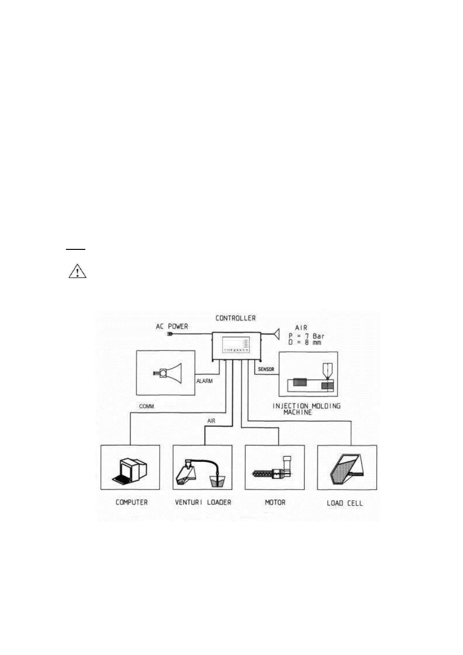
3.3.1 Connect the following (see Fig 5: Connections diagram):
a) Connector J1-
"Load cell" input, to the load cell (“Load cell” cable).
b) Connector J2-
"Alarm" output, to the alarm device (“Alarm” cable).
c) Connector J3-
"Sensor" input to the Injection machine (“Sensor” cable).
Notes:
1) For connection options for this cable, see Chap. 3.3.2 "Sensor cable wiring
options"
2) When the "Micro" (Pellet Counting) option is integrated, the cable is split into two
cables
– one from the injection machine (supplying the IMM signals) and the other
one from the revolution sensor (supplying the "screw revolutions" data).
d) Connector J4-Communication port to required device (optional)
e) Connector J5-
Motor control outlet to the motor cable (“Motor” cable).
f) Connector 230V to the mains.
Note: Good grounding of the injection machine is required to ensure proper feeder operation.
Warning
Do not connect or disconnect the motor cable when the power is "on"
Fig 5: Connections diagram