2 releasing the load cell, 3 venturi loader installation (see fig. 2), 4 control unit mounting – Sterlco SF1000 Gravimetric Additive Feeder User Manual
Page 8
8
3.2.2 Releasing the load cell (see Appendix A)
When the unit leaves the factory, the load cell is locked by its protecting device, to prevent
any damage to the load cell during transportation and installation.
After installation and before starting to operate the feeder, release the limiting pin of the
protecting device from its "locked position" to "unlocked position"; otherwise the load cell will
not be able to function.
See Appendix A for unlocking instructions after installation.
Important:
Always re-lock the safety device whenever the Sterling SF-1000 is dismantled from the
injection or extrusion machine and being moved to another location or machine.
Note that there is no guarantee for the load cell for any mechanical damage, or
damage caused by an overload.
3.2.3 Venturi loader installation (see Fig. 2)
a) Connect the Venturi suction tube (19) to the fee
der’s additive/color loading inlet (17) with
the flexible 25 mm dia. loading pipe (18).
Note: The maximum pipe length should not exceed 3 meters and the maximum difference
between the end of the Venturi suction tube and the top of the feeder-loading inlet should
not exceed 2.5 meters.
b) Connect the pneumatic air inlet (20) of the Venturi tube to the air outlet of the Air valve
(P1) on the back panel of the controller.
c) Connect a 6-8 AT air supply to the air inlet of the Air valve of the controller.
d) Dip the Venturi suction tube into the main color/additive container (21). Verify that the tube
is straight and not twisted or bent; otherwise it might disturb the suction process.
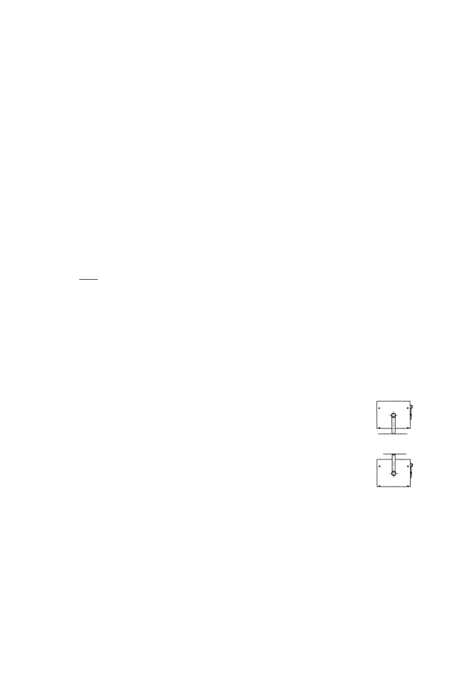
3.2.4 Control unit mounting
Fix the control unit by its mounting arm in one of the following options:
Option A (bottom surface):
Option B (top surface):