3 supplied hardware, Ufb standard equipment, Ufb optional equipment – Dwyer UFB User Manual
Page 7: General description
1: General Description
3
The system can be set up to operate in one of four modes, determined mainly by the pipe diameter and the type
of transducer set in use. The diagram in Figure 1.1 illustrates the importance of applying the correct separation
distance between the transducers to obtain the strongest, and therefore most reliable, signal.
1.3
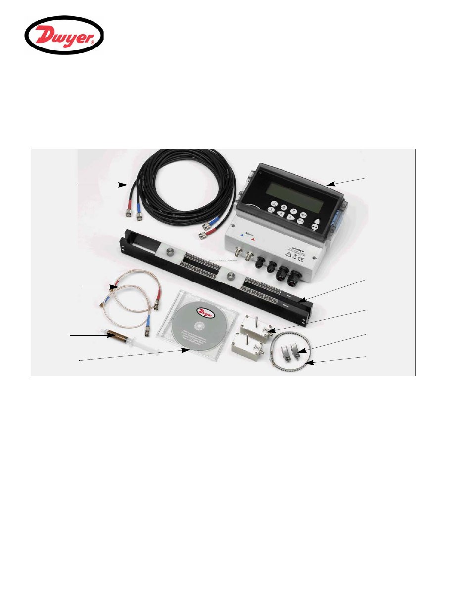
Supplied Hardware
The supplied UFB components are shown in Figure 1.2.
Figure 1.2 Standard UFB equipment
UFB Standard equipment
• Instrument with backlit graphic display.
• Transducer cables (x2) 16.5 feet (419 mm) in length.
• High temperature interface cables (x2).
• Transducers ‘A-ST’ x2 (UFB-A) for use with pipes ranging 0.5 to 4.5
inches (13 to 115 mm).
• Transducers ‘B-ST’ x2 (UFB-B) for use with pipes ranging 2 to 79 Inches (50 to 2000 mm).
• Transducer holder for use with ‘A’ or ‘B’ transducers.
• Steel bands used to secure the transducer holder to the pipe.
• Acoustic couplant.
• User documentation.
UFB Optional equipment
• Transducer set 'D' can be used for monitoring pipes of 59 inches to 197 inches (1500 to 5000 mm) outside
diameter, over a temperature range -4°F to +176°F (-20°C to +80°C). This optional kit is supplied in a
separate case and includes the type 'D' transducers together with ratchet straps and holders for attaching
the transducers to the pipe.
Acoustic
Steel
Transducer
Transducers
(Sensors)
UFB
Instrument
Mounting
High
Transducer
Cables (x2)
User
Documentation
holder
Temperature
Interface
Cables (x2)
Couplant
Applicator
(Ax2, or Bx2)*
Clamps (x2)
Bands (x2)