2 mounting the instrument, Installation, Mounting details – Dwyer UFB User Manual
Page 11: Cable connections
2: Installation
7
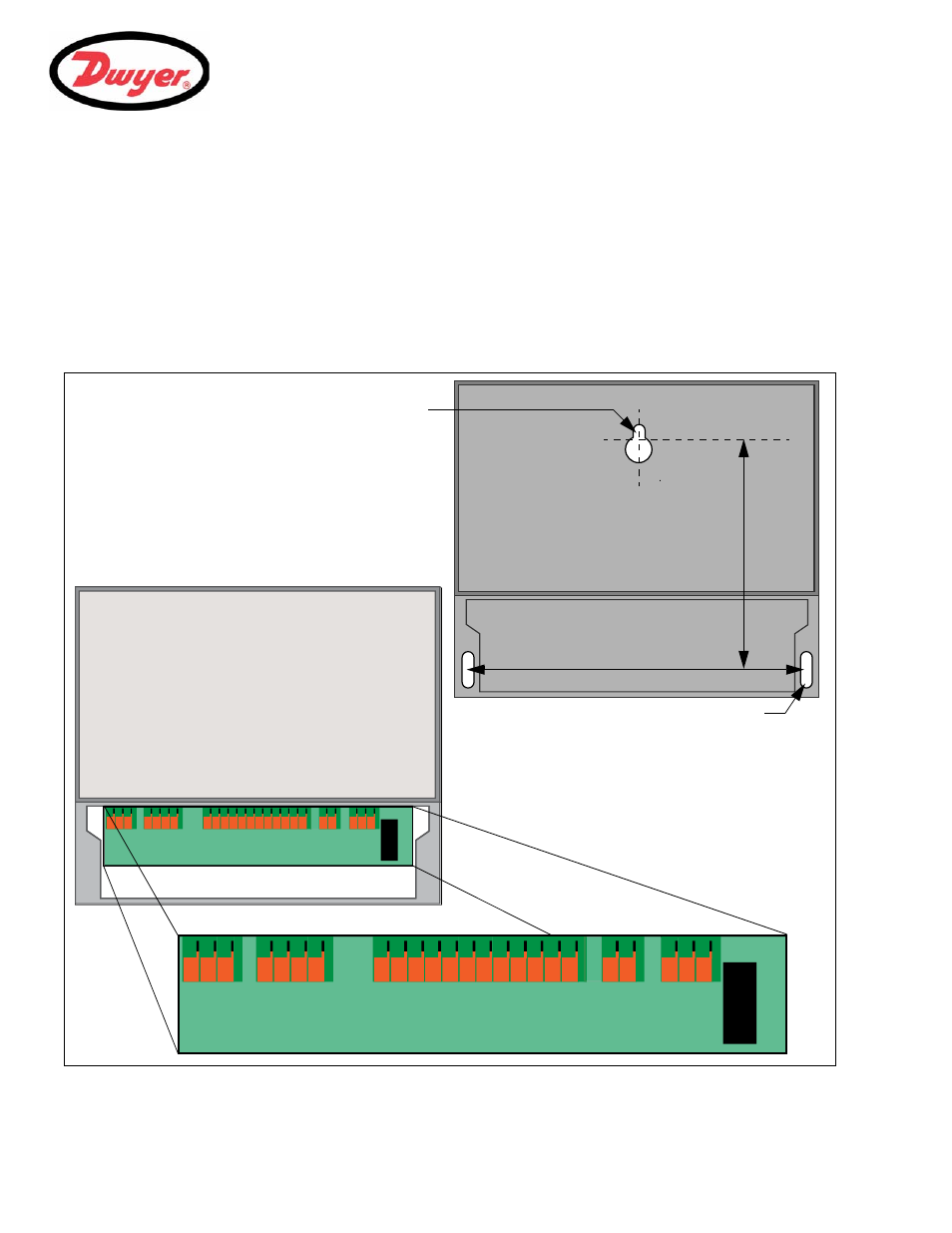
2.2.2 Mounting the instrument
Ideally, the UFB enclosure should be fixed to a wall using three screws – see Figure 2.2.
1.
Remove the UFB terminal cover.
2.
Fix a screw into the wall at the required point to align with the mounting keyhole on the back of the enclosure.
3.
Attach the enclosure to the wall using the keyhole screw mounting.
4.
Align the enclosure then mark out the positions for the two remaining screw fixings through the slots near the
bottom corners of the enclosure. Then remove the enclosure, and drill (and plug) the two fixing points.
5.
Clear the site of any dust/debris, then mount the enclosure on the wall.
Figure 2.1 UFB Mounting and connection details
GN
D
Tx
D
Rx
D
mA+
mA
-
PU
LS
E+
PU
LSE-
AL
AR
M1
+
AL
AR
M
1
-
AL
AR
M2
+
AL
AR
M
2
-
EX
PI
O#
1
EX
PI
O#
2
EX
PI
O#
3
EX
PI
O#
4
EX
PI
O#
5
EX
PI
O#
6
EX
PI
O#
7
EX
PI
O#
8
24
V
+
24
V
-
23
0V
-L
23
0
V
-N
230
V
-E
GND
Tx
D
RxD
mA+
mA-
PU
L
S
E+
PU
L
S
E-
AL
AR
M
1
+
AL
AR
M
1
-
AL
AR
M
2
+
AL
AR
M
2
-
EX
P
IO
#
1
EX
P
IO
#
2
EX
P
IO
#
3
EX
P
IO
#
4
EX
P
IO
#
5
EX
P
IO
#
6
EX
P
IO
#
7
EX
P
IO
#
8
24
V
+
24
V
-
23
0V -L
23
0
V
-N
23
0
V
-E
FU
S
E
4.5in
7.8in
Screw Slot
Keyhole
Mounting Details
The instrument should be
securely wall-mounted using the
three fixing points shown.
Cable connections
All power and control cables enter
through cable glands located on the
bottom of the instrument and connect
to terminal blocks as shown.