3 installing the ultrasonic transducers, 1 transducer positioning, Installation – Dwyer UFB User Manual
Page 13
2: Installation
9
2.3
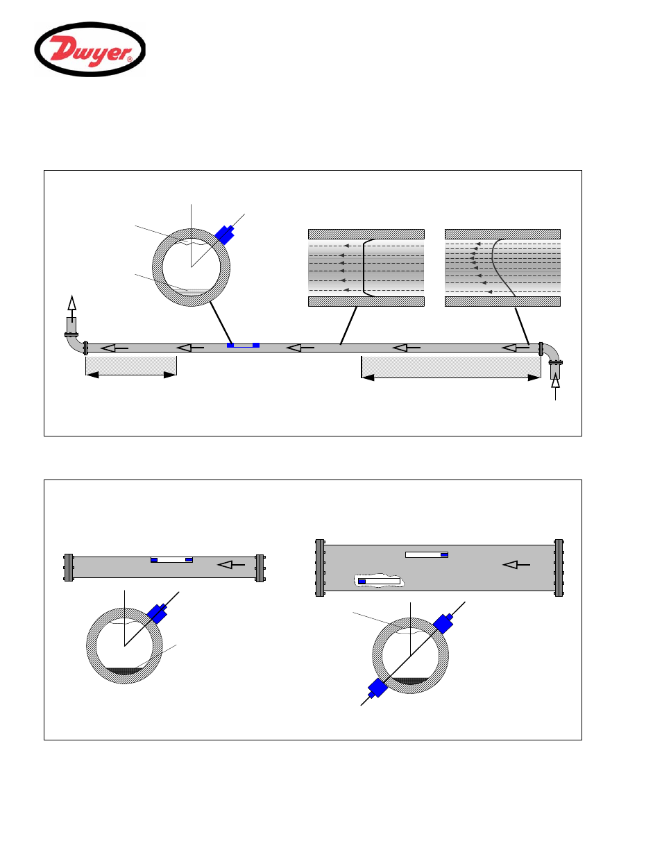
Installing the Ultrasonic Transducers
2.3.1 Transducer
positioning
Figure 2.2 Locating the transducers
Figure 2.3 Transducer holder attachment (reflex vs. diagonal mode)
The UFB equipment expects a uniform flow profile as a distorted flow will produce unpredictable measurement errors. Flow
profile distortions can result from upstream disturbances such as bends, tees, valves, pumps and other similar obstructions.
To ensure a uniform profile, the transducers must be mounted a sufficient
distance away from any cause of distortion.
Flow
Valid transducer location
10 x Diameter
20 x Diameter
45°
Uniform Flow Profile
Distorted Flow Profile
Possible
sludge
Air
Flow
Transducer
Holder
45°
In many applications an even flow velocity profile over a full 360° is unattainable due to, for example, air turbulence at the
top of the flow and possibly sludge in the bottom of the pipe. Experience has shown that the most consistently accurate
results are achieved when the transducer holders are mounted at 45° with respect to the top of the pipe.
Possible
sludge
Air
Reflex Mode
Diagonal Mode*
Transducer
Transducer
Transducer Holder 2
Transducer Holder
Transducer Holder 1
Transducer Holder 2
45°
*Note: when using the UFB in the ‘diagonal’ mode an additional transducer holder and fixing kit is required.
Holder
Holder 1