Installation – Advanced Protection XRL User Manual
Page 8
INSTALLATION
Pre-Plan your installation. You will need to accomplish the following:
▪
Meet all National and Local codes. (NEC
®
Article 285 addresses SPDs)
▪
Mount SPD as close to panel or equipment as possible to keep leads short.
▪
Ensure leads are as short and straight as possible, including neutral and ground.
Consider a breaker position that is closest to the SPD and the panel’s neutral & ground.
▪
Suggested breaker & conductor size is 60A-30A with 6 AWG.
▪
Make sure system is grounded per NEC
®
and clear of faults before energizing SPD.
Certain options or implementations require extra consideration. See appropriate sections
within this manual:
▪
Line Side Installation (page 4)
▪
Internal or Integral Mount Installation inside electrical gear (page 7)
▪
Disconnect Switch Option (page 7)
▪
Flush Mount Option (page 6)
▪
Retro-fit where no breaker positions are available (page 11)
▪
UL/NEMA 3R Drain Holes (page 10)
1. Use a voltmeter to check all voltages to ensure correct SPD.
2. If SPD has Dry Contact, Remote Monitoring or Remote Display, pre-plan their installation.
3. Remove power for panel. Confirm panel is deenergized.
4. Identify connection/breaker location and SPD location.
5. Make sure leads are short. Reducing inches matters. Pretend that connector leads cost you
$1000/foot to make leads short!
Installation Tips: SPD module is mounted on backplane within its enclosure. In many cases, the backplane assembly
can be unbolted and rotated in two or four directions to yield shortest leads. See Fig 8. Carefully disconnect ribbon
cable(s) and unbolt backplane assembly. Various configurations have limited work space. Please be patient. Installation
may be easier if disconnect switch is temporarily removed from DIN-rail, or module/backplane is temporarily removed.
6. Remove an appropriately sized knockout from panel. Create an appropriately sized and lo-
cated hole in the SPD enclosure.
7. Mount SPD. Connect to equipment using an approved wiring method, including seals appropriate for
the enclosure rating. Carefully reinstall backplane or disconnect switch as appropriate.
8. Connect conductors as appropriate – short and straight as possible
(Note that Hi-Legs are Phase B).
9. Label or mark conductors as appropriate
(neutral: white, ground: green, energized: black, hi-leg: orange).
10. Make sure system is bonded per NEC
®
and is clear of hazards or faults before energizing (N-G
bonding not per NEC
®
will fail SPDs: #1 cause of SPD failures).
11. Energize and confirm proper operation of indicators and/or options. If Red LED flashes &
Audible Alarm cycles, deenergize immediately and call for help.
8
Figure 6
A
B
C
G
N
BREAKER
Phase C
Service
Phase B
Phase A
Surge Counter
Advanced Protection Technologies
Silence
Test
Count
Reset
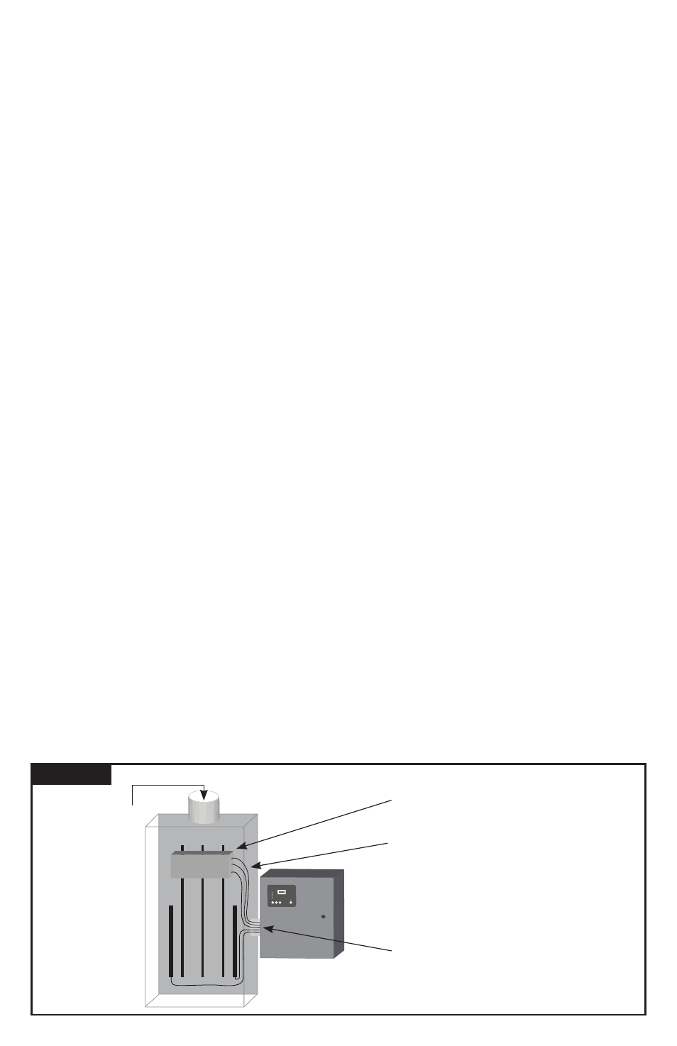
TYPICAL PANEL INSTALLATION
▪
Use closest breaker to SPD
▪
Locate SPD close to intended breaker
▪
Keep Leads Short as Possible
▪
Avoid Sharp Bends
▪
Outdoor installation requires appropri-
ate weather sealing at nipple (o-ring,
sealing condulet, etc.)
To Protected Loads