Table 1: model number decoder, Figure 2 – Advanced Protection XRL User Manual
Page 3
3
Precautionary Statement Regarding SPDs on Ungrounded Systems
Caution – Ungrounded systems are inherently unstable and can produce
excessively high line-to-ground voltages during certain fault conditions. During
these fault conditions, any electrical equipment including an SPD, may be
subjected to voltages which exceed their designed ratings. This information
is being provided to the user so that an informed decision can be made
before installing any electrical equipment on an ungrounded power system.
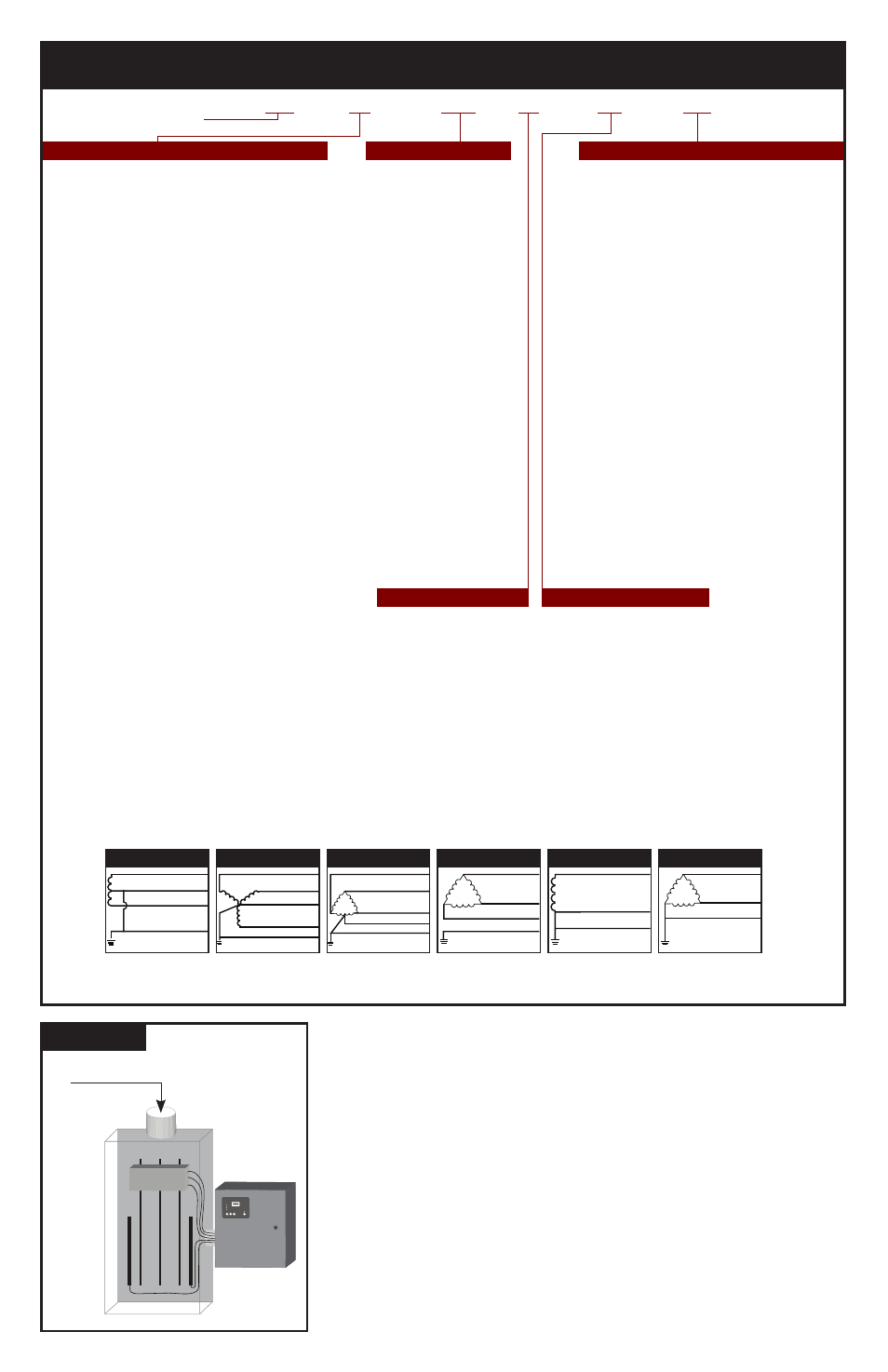
Cascade Surge Protection
For optimum surge protection, cascade or staged surge suppression should
be implemented at the service entrance and downstream locations as
appropriate. Known or expected surge sources, as well as sensitive loads,
should also have localized surge suppression. For interconnected electronic
loads (data cabling), SPDs should also be utilized to protect the devices on
either end of the interconnecting data cables.
Figure 2
A
B
C
G
N
BREAKER
Phase C
Service
Phase B
Phase A
Surge Counter
Advanced Protection Technologies
Silence
Test
Count
Reset
TYPICAL PARALLEL
CONNECTED SPD ON
ELECTRICAL PANEL
To
Protected
Loads
TABLE 1: MODEL NUMBER DECODER
Do not create model numbers from this chart as all features are not available on all models
Transient Eliminator
Voltage Code for Electrical System Model Family
Options
TE
02
XAS
20
E1
XD
X = Surge Counter, six-digit LCD counter
includes maintenance-free Eprom memory
backup
Z = Surge Counter, plus External Surge
Counter Signal
E = Remote Locatable Display on 6 ft Cable
custom cable lengths available
M = Mount Display on SPD instead of cable
F = Noise Filtering - Extended Range &
Attenuation
D = Rotary Disconnect Switch
Bussman, UL98
T = Thru-door Rotary Disconnect Switch
Bussman, UL 98, NEMA 1/12/3R only
K = Rotary Disconnect Switch
Katco, UL 508
S = Thru-door Rotary Disconnect Switch
Katco, UL 508, NEMA 1/12/4 only
Delete Options
L = Delete L-N Protection (reduces kA rating)
G = Delete L-G Protection (reduces kA rating)
N = Delete N-G Protection (reduces kA rating)
J = Delete Noise Filter
Other Available Systems - Confirmation encouraged:
15 = 254/127V Split Phase - 1Ø 3W+Grnd, (Fig 1)
18 = 480/240V Split Phase, or Two legs of Wye, (Call)
21 = 220Y/127V Wye - 3Ø 4W+Grnd (Fig 2)
41 = 520Y/300V Wye - 3Ø 4W+Grnd (Fig 2)
42 = 415Y/240V Wye - 3Ø 4W+Grnd (Fig 2)
43 = 400Y/230V Wye - 3Ø 4W+Grnd (Fig 2)
44 = 440Y/250V Wye - 3Ø 4W+Grnd (Fig 2)
51 = 480V B Corner Grnd Delta, 3Ø 3W+Grnd (Fig 6)
06 = 240V Delta - 3Ø 3W+Grnd (Fig 4)
61 = 240V B Corner Grnd Delta, 3Ø 3W+Grnd (Fig 6)
07 = 380Y/220V Wye - 3Ø 4W+Grnd (Fig 2)
09 = 600V Delta - 3Ø 3W+Grnd (Fig 4) & HRG Wye
(Available: 100kA, 150kA, 200kA, 250kA)
91 = 600V B Corner Grnd Delta, 3Ø 3W+Grnd (Fig 6)
(Available: 100kA, 150kA, 200kA, 250kA)
11 = 120V Single Phase (Fig 5)
12 = 240V Single Phase (Fig 5) - Not split phase
13 = 127V Single Phase (Fig 5)
14 = 300V Single Phase (Fig 5)
16 = 277V Single Phase (Fig 5)
17 = 480V Single Phase (1 Hot, 1 Neu, 1 Grnd) (Fig 5)
10 = 100kA/Phase
15 = 150kA/Phase
20 = 200kA/Phase
25 = 250kA/Phase
30 = 300kA/Phase
31 = 300kA/Phase
40 = 400kA/Phase
45 = 450kA/Phase
50 = 500kA/Phase
60 = 600kA/Phase
80 = 800kA/Phase
90 = 900kA/Phase
1K = 1000kA/Phase
XAS = External Mount SPD
Standard Modes
XAL = External Mount SPD
10 Mode
XBS = External Mount SPD
Two Modules
Standard mode
XBL = External Mount SPD
Two Modules
10 Mode
For Internal Mount
(No Enclosures):
XRS = Component SPD,
UL Recognized
Standard Modes
XRL = Component SPD,
UL Recognized
10 Modes
XWS = Component SPD,
UL Recognized
Standard Modes
XWL = Component SPD,
UL Recognized
10 Modes
Common North American Systems:
01 = 240/120V Split Phase - 1Ø, 3W+Grnd, (Fig 1)
02 = 208Y/120V Wye - 3Ø 4W+Grnd, (Fig 2)
03 = 240/120V High Leg Delta (B High), (Fig 3)
04 = 480Y/277V Wye - 3Ø 4W+Grnd, (Fig 2)
05 = 480V Delta - 3Ø 3W+Grnd, (Fig4) & HRG Wye
08 = 600Y/347V Wye - 3Ø 4W+Grnd, (Fig2)
E1 = NEMA 1/12/3R/4
4X = NEMA 4X Non-Metallic
4S = NEMA 4X Stainless Steel
FM = NEMA 1 Flush Mount
P1 = NEMA 1 pullbox ‘indoor'
Enclosure Rating
Figure 1
Figure 2
Figure 3
Figure 4
Figure 5
Figure 6
SPLIT
2 Hots, 1 Neu, 1 Grnd
HI-LEG DELTA (B High)
3 Hots, (B HIGH),
1 Neu, 1 Grnd
SINGLE POLE
1 Hot, 1 Neu, 1 Grnd
WYE
3 Hots, 1 Neu, 1 Grnd
DELTA & HRG WYE
3 Hots, 1 Grnd
CORNER GROUND
DELTA (B grounded)
2 Hots, 1 Grnd
Hot (BLK)
Hot (BLK)
Neutral (WHT)
V
V
}
}
Ground (GRN)
}
Phase A (BLK)
Phase B (BLK)
Neutral (WHT)
Phase C (BLK)
Ground (GRN)
A
C
N
V
B
Phase A (BLK)
Phase B (ORNG)
Neutral (WHT)
Phase C (BLK)
Ground (GRN)
}
V
V
}
Neutral (WHT)
Hot (BLK)
Ground (GRN)
Phase A (BLK)
Phase C (BLK)
Phase B (BLK)
Ground (GRN)
}
V
Phase A (BLK)
Phase C (BLK)
Ground (GRN)
V
}
Surge Current Rating