Figure 8 nema 3r drain holes figure 9, Diagnostic display panel – Advanced Protection XRL User Manual
Page 10
10
OPERATION
Diagnostic Display Panel
All indicators and controls are located on the diagnostic
panel. The diagnostic panel is located on the front of the SPD
enclosure or behind the door on certain optional enclosures.
Each phase features a Green LED indicator. Green LEDs
indicate correct operation.
If an inoperative condition were to occur, the built-in audible
alarm will sound and the red Service LED will illuminate.
This indicates that the unit needs evaluation by a qualified
electrician or technician. Until a qualified person evaluates
the unit, press Alarm Silence to silence the alarm. (The
LED above Alarm Silence illuminates when the alarm
is deactivated. Normal operation occurs with the Alarm
Silence LED extinguished.) The red Service LED will
remain illuminated even though the Audible Alarm has been
silenced. Test tests the red Service LED, the Audible Alarm,
and changes the state of Dry Contacts (if equipped).
If LEDs are illuminated in a manner that suggests
contradictory information, there may be an internal logic
problem and the unit needs replaced. If none of the LEDs
are illuminated, the unit may not be installed correctly. For
troubleshooting assistance, please contact APT Technical
Support at (800) 237-4567.
Surge Counter Option
The surge counter registers the number of transient
overvoltages on all L-N and L-G modes since the counter
was last reset. The counter is inductively coupled from each
mode of protection. It increments upon significant current
change in a short time period (large di/dt).
The surge counter includes Count and Reset buttons on
the touchpad display. Pressing Count adds one count.
Pressing Reset clears the counter’s memory and sets the
display to zero.
The counter includes an Eprom memory chip to store the
surge count in the event of a power loss. The Eprom requires
no maintenance giving it an advantage over replaceable
batteries. The surge counter display will be blank if all power
is lost to the SPD but will retain the last count shown on the
display once power is returned.
NEMA 3R Drain Holes for Standard Steel Enclosure
In order to maintain a UL 3R rating, two 0.25” (6mm) holes
must be drilled in opposite corners of the bottom surface
of the enclosure. Take care to not damage internal SPD
components. Remove any drilling remnants. (Do not perform
on other enclosures or ratings.)
Figure 8
NEMA 3R DRAIN HOLES
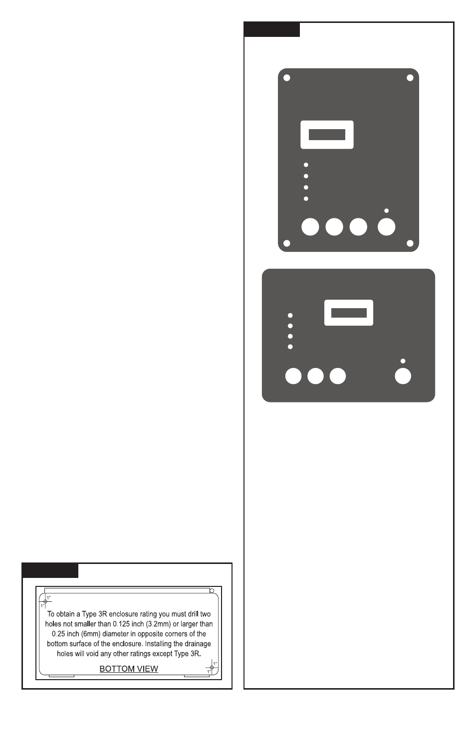
Figure 9
Phase A, B & C: Green LED indicators—one per
phase. Green is good. Out indicates problem. Every
suppression element in this SPD is monitored. (N-G
indicates on Phase A)
Service LED (Red): LED illuminates in the event
of problems. This indicator is logic-connected to the
Phase LEDs. Should a Phase LED go out the Service
LED will illuminate and the Audible Alarm will sound.
Test: Tests red Service LED and Audible Alarm, and
changes state of Dry Contacts.
Alarm Silence: Turns Audible Alarm off. (Alarm is
deactivated when the Silence LED is illuminated.)
Surge Counter Count: (if equipped) Increments
optional surge counter by one. (+1)
Surge Counter Reset: (if equipped) Resets optional
surge counter to zero. (0)
DIAGNOSTIC DISPLAY PANEL
Phase B
Phase C
Service
Phase A
Advanced Protection Technologies
Test
Count
Reset
Silence
Surge Counter
Phase C
Service
Phase B
Phase A
Surge Counter
Advanced Protection Technologies
Silence
Test
Count
Reset