Rotating module design allows for shorter leads, Figure 5, Figure 4 internal mount display dimensions – Advanced Protection XRL User Manual
Page 7
7
the wall cavity 6 1/16” from the wall face such that the SPD
is supported from its back. Note the mounting holes on the
back flange. Also note that the SPD weighs 22-52 lbs. Be
careful not to drop the SPD into the wall.
Disconnect Switch
(Opt. on XA, Std. on XB)
The disconnect switch provides manual disconnection
means for phase conductors and the neutral conductor.
Ground is not switched.
Special care should be taken while pre-planning installation
to ensure that leads are as short as possible. Most XA’s &
XB’s in ‘square’ enclosures have backplanes that can be
removed and repositioned to reduce leads. See Figure 8.
(Models with rectangular enclosures may be repositioned
by inverting only.) (Excludes thru-door handle options.)
There is limited working space around the Disconnect
Switch. This is a consequence of reducing internal size
and lead lengths. Please be patient.
Disconnect switch will accept 6 AWG to 1/0 AWG, with 6
AWG preferred. Torque connections to 18 inch-pounds.
OVER-TORQUING connections WILL BREAK the
Disconnect Switch and will not be covered by warranty.
The disconnect switch is mounted on DIN-rail. It may be
removed by gently pulling out the mounting tab at the
bottom of the switch assembly.
APT is one of few SPD manufacturers that make Disconnect
Switches available as a fully UL qualified option. The
Disconnect Switch was included during UL certification
and testing. The Short Circuit Current Rating posted on
the UL label of the SPD includes the Disconnect Switch
and supersedes any rating on the individual Disconnect
Switch. When used in a Type 1 line-side application, the
SPD including its Disconnect Switch has been UL tested
and approved. Further evaluation is not required by UL, nor
is a separate UL 98 rated switch required.
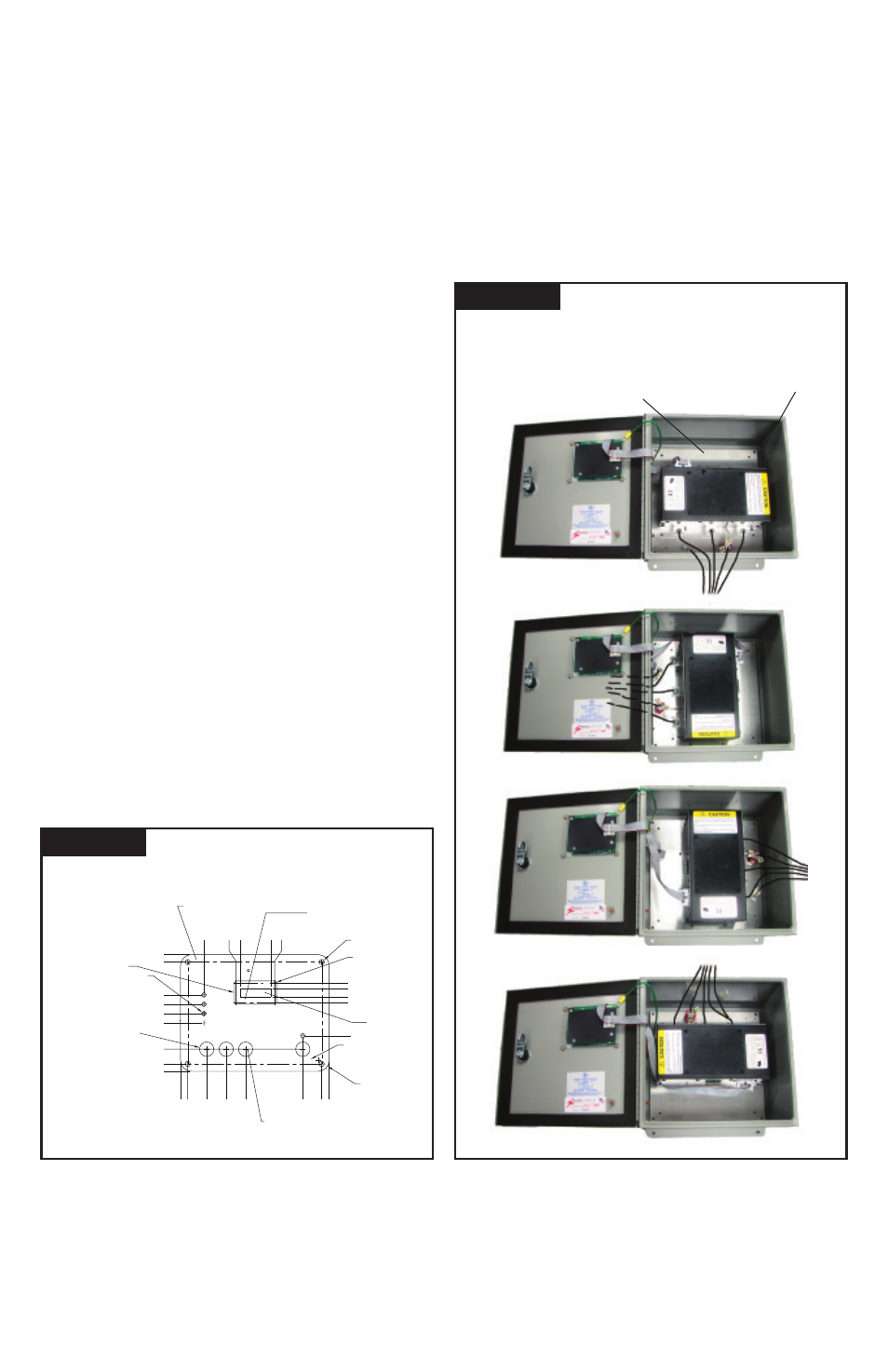
Figure 5
Diagnostic Cable Connector
ROTATING MODULE
DESIGN ALLOWS FOR
SHORTER LEADS
Mounting Screws
in Corners
Figure 4
INTERNAL MOUNT
DISPLAY DIMENSIONS
0.000
0.000
1.384
1.699
2.014
2.329
3.437
0.951
4.618
0.559
0.250
4.875
0.250
3.690
0.180 THRU 4 PL.
R0.375 4 PL.
Count
Reset
3.963
1.798
2.861
CLEAR WINDOW TYP.
Phase C
Service
Phase B
Phase A
Test
Silence
Surge Counter
0.497
0.654
1.324
1.994
Ø.50 BLACK BORDER TYP.
1.660
BLACK LETTERS (SURGE COUNTER)
BACKGROUND TO BE PANTONE 441C
RED LETTERS (ALARM SILENCE ONLY)
PANTONE 185C
BACKGROUND TO BE PANTONE 445C
PANTONE 441C 4 PLACES
R0.062 4 PL.
BLACK BORDER
2.999
2.077
2.737
2.545
2.269
0.125 TRANSLUCENT WINDOW 5 PL.
Module Rotation Feature
Installation lead wire length must be minimized because
longer leads hurt performance. Lead length may be reduced
by rotating the module inside the enclosure. SPD ships with
terminals pointing down. If installation lends itself toward
other orientation, the module’s aluminum backplane can be
unscrewed and reoriented. For example, if leads enter from
top, rotate module assembly such that leads are shortest.
Be careful with ribbon cable connector and take care to
retighten screws & secure ribbon cable. Mounting screws
are in four corners. Rectangular enclosures may be rotated
up or down only. See Figure 5.