Standard & type 4s mechanical drawings – Advanced Protection XRL User Manual
Page 13
13
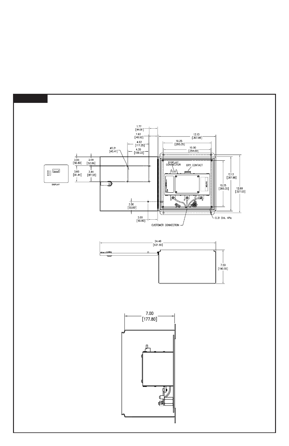
Figure 12
STANDARD & TYPE 4S MECHANICAL DRAWINGS
If an inoperate condition were to occur, the diagnostic
display will indicate a problem via red Service LED, audible
alarm and dry contact change. Operation is identical to
XA, XR or XW series.
Each XB module includes a red LED above the phase
connection tabs, near the inter-module diagnostic wiring.
An illuminated red LED indicates the damaged module.
Extra Information: Should one damaged module be
removed, the SPD can still function correctly with one
module. If the diagnostic display cable was connected
to the removed module, reconnect the cable to the other
module’s quick release connector. The diagnostic display
will function correctly. (XB’s with Type 4X or 4S enclosures
have the diagnostic display mounted inside the enclosure
on the right side module. If this module is removed, the
diagnostic display may be moved to the other module.
Remove the display’s four screws, the display and
appropriate internal ribbon cable. Remove blank cover from
the remaining module and reassemble in reverse order.)