Step 3, Step 2 – Advanced Protection XRL User Manual
Page 6
6
For sensitive electronics and computer systems, we
recommend that the ground impedance measurement be
as low as possible. When metallic raceway is used as an
additional grounding conductor, an insulated grounding
conductor should be run inside the raceway and sized per
the NEC
®
. Adequate electrical continuity must be maintained
at all raceway connections. Do not use isolating bushings
to interrupt a metallic raceway run.
A separate isolated ground for the SPD is NOT recommended.
Proper equipment connections to grounding system and
ground grid continuity should be verified via inspections and
testing on a regular basis as part of a comprehensive electrical
maintenance program.
On 4-Wire Power Systems, neutral to ground bonding (Main
Bonding Jumper) must be installed per the NEC
®
. Failure
to do so WILL damage SPDs.
Internal Mounting of XR and XW Component SPD
XR’s and XW’s are essentially XA’s without enclosures. XR’s
and XW’s are intended for installation within host electrical
equipment having suitable enclosures.
The experienced integrator will appreciate the simplicity
of XR/XW. XR/XW’s are Type 4 SPDs and have been
evaluated by UL for use as Type 1 (or Type 2) SPDs
when installed in appropriate enclosures. All UL required
safety testing is complete without needing additional
safety apparatus. Contact factory for UL file Engineering
Considerations. Mount SPD in appropriate enclosure,
mount Diagnostic Display in appropriate location and follow
appropriate instructions, including short leads. UL evaluation
within your completed product should be easy and trouble
free. Do not Hi-Pot test with SPD in circuit.
In many instances, a disconnecting means is appropriate
for future service. A breaker serves this function, as well
as provides overcurrent protection to the connecting
conductors. If a breaker or optional Disconnect Switch are
not used, consider a disconnect or safety switch having
appropriate SCCR rating including any required overcurrent
protection. Line side is likely to require a UL 98 switch where
load side is likely to require a UL 508 (or UL 98) switch.
This may be more time consuming, more expensive and
physically larger than anticipated. APT offers an optional
Disconnect Switch that has been UL evaluated as part of the
SPD. The optional Disconnect Switch is fully engineered and
almost certainly easier, smaller and less expensive. Please
contact APT Technical Support as appropriate.
Mounting Diagnostic Display: Mount the Display in a
user-friendly location, with consideration to weather and
vandalism. Dimensions are in Figure 4 (page 7). A Display
with a 6’ connector cable is typically included. Longer lengths
are available. The Display is also mountable directly on the
XR/XW module (shorter cables required). The standard
Display includes mounting thru-holes and is not weather
resistant. Contact factory for weather resistant NEMA 4 rated
Display (with mounting studs instead of thru-holes and label
material including UL 746C(f1) & UL 94-5VA flame rating).
UL 1283 required language concerning the installation
of EMI Filters
a) An insulated grounding conductor that is identical in size
and insulation material and thickness to the grounded and
ungrounded circuit supply conductors, except that it is green
with or without one or more yellow stripes, is to be installed
as part of the circuit that supplies the filter. Reference should
be made to Table 250-122 of the National Electrical Code
regarding the appropriate size of the grounding conductor.
b) The grounding conductor mentioned in item a is to
be grounded to earth at the service equipment or other
acceptable building earth ground such as the building frame
in the case of a high-rise steel-frame structure.
c) Any attachment-plug receptacles in the vicinity of the
filter are to be of a grounding type, and the grounding
conductors serving these receptacles are to be connected
to earth ground at the service equipment or other acceptable
building earth ground such as the building frame in the case
of a high-rise steel-frame structure.
d) Pressure terminal or pressure splicing connectors and
soldering lugs used in the installation of the filter shall be
identified as being suitable for the material of the conductors.
Conductors of dissimilar metals shall not be intermixed in a
terminal or splicing connector where physical contact occurs
between dissimilar conductors unless the device is identified
for the purpose and conditions of use.
Optional Flush Mount Installation Considerations
The XA & XB are approximately 6” deep. The unit will not
mount flush unless there is at least 6” of depth clearance.
The XA & XB are not designed to mount flush on a typical
2 x 4 stud wall.
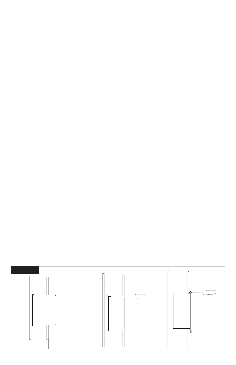
Back Flange Mounting: Mount as close as possible to
protected panel. Create a wall opening slightly larger than
SPD. See Figure 4. Configure a robust backing plate inside
FLUSH MOUNT INSTALLATION
Figure 3
STEP 2:
Mount SPD
STEP 3:
Install Flush
Mount Plate
& Cover
Cutout slightly larger than
SPD base
Mounting Plate
6 1/16” from
outside of front
wall
STEP 1:
Prepare Wall
- Must support
25-55lbs