Advanced Protection XRL User Manual
Page 12
accelerated on Wye systems where SPDs are designed
for grounded systems. (SPDs for ungrounded systems
generally have higher MCOV to allow for L-G voltage
fluctuations.) Failures of this nature are not defects in the
SPDs workmanship or material. This is an installation error,
not a warrantable situation.
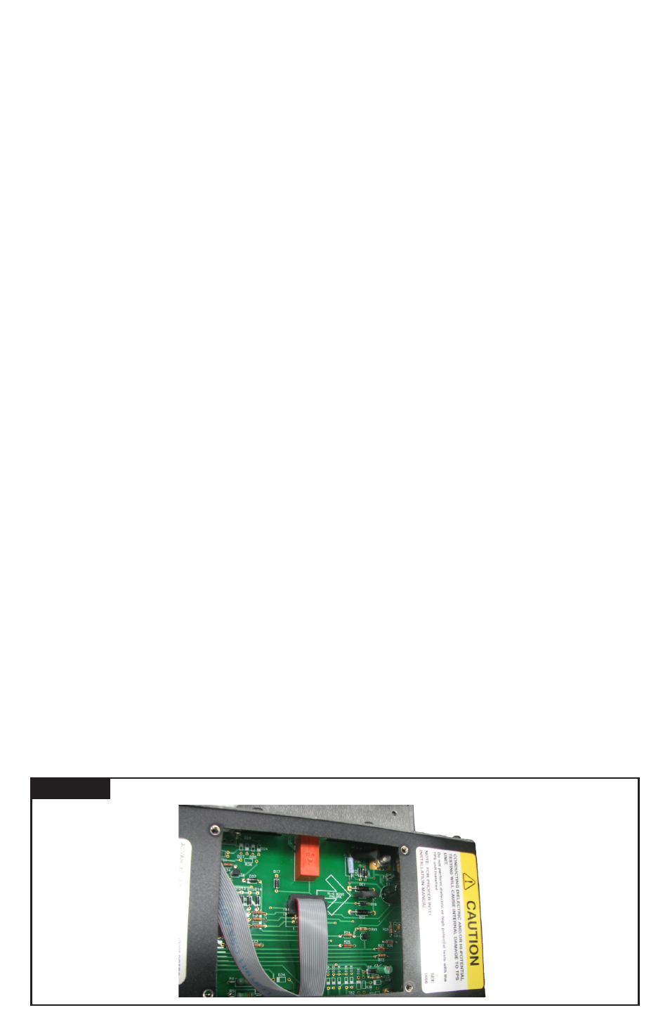
A differential voltage circuit monitors neutral to ground
voltage. When N-G voltage becomes excessive, a shrink-wrap
covered resistor will heat. After several minutes, the shrink
wrap will shrink around the resistor. This diagnostic tool will
not detect instantaneously excessive N-G voltages. If shrunk
or tampered with, the warranty is voided. (When the SPD
is deenergized, this resistor can be accessed by qualified
personnel under the display plate cover. See Figure 11.
Module Replacement & Service
The module(s) is field replaceable. Deenergize SPD, confirm
with appropriate measurement equipment and discharge
internal capacitance to ground. Mark locations and carefully
disconnect diagnostic cables, dry contact connections, phase
conductors, unplug parallel connections on XB models, etc.
Depending on model, module may be bolted to backplane or
the backplane may be part of the module assembly. Remove
module/backplane. Reinstall in reverse order.
There are no user serviceable parts inside the module. We
strongly recommend against disassembly.
Modules may be returned to the factory for factory service,
qualification and return. Please contact the factory at
(800) 237-4567 for assistance.
Display Replacement
The display is field replaceable. Deenergize SPD,
confirm with appropriate measurement equipment and
discharge internal capacitance to ground. Mark locations
and carefully disconnect diagnostic cables, contacts,
connecting conductors, etc. Unbolt display and replace.
Reinstall in reverse.
Note that a sealing gasket between the display and the
enclosure is a key component ensuring weather resistance.
Replace the gasket whenever the display is removed.
XB Series with two modules
The XB features two redundant modules. One diagnostic
display monitors both modules simultaneously via the
parallel wire connections between the modules. These
connectors plug in to each module, transfering information
to internal logic on-board both modules.
12
MAINTENANCE
SPDs require minimal maintenance. We recommend periodic
inspection of diagnostic indicators to ensure proper operation.
We also recommend keeping the SPD clean as appropriate.
Troubleshooting & Service
Please contact us for any service related issues. We want
to take care of any problems.
Quality SPDs are designed and tested to withstand severe
duty. However, there are various electrical anomalies that
SPDs cannot protect against. These are generally Sustained
Overvoltages also known as Temporary Overvoltages
(TOVs). In this context, Sustained Overvoltages may be only
a few cycles. Failed SPDs tend to be symptoms, not root
causes. A failed SPD should be treated as a ‘canary in the
coalmine’ suggesting further investigation as there may be
a larger issue at play. Regardless of cause, SPDs attempt
to protect their load until failure.
As noted above, the single largest ‘killer’ of SPDs is
reference to ground issues. If the SPD shows problems on
startup, there is reasonable chance of bonding/grounding/
misapplication issue. This permanently damages the unit.
If not corrected, it will happen again.
Tip: Visually confirm N-G bonding. Be aware that a voltmeter
measuring N-G can be misleading. For example, N-G voltage
could read 0V because neutral and ground are at the same
potential by happenstance, not because they are bonded.
Visually confirm bonding.
Tip: Experience indicates that regulation-challenged generators
can cause Sustained Overvoltages, as well as ungrounded
generators, and/or unusual load transfer systems.
Abnormal N-G Voltage Indicators
This SPD include N-G voltage indicators and a tattletale.
If the SPD detects excessive N-G voltage, it will blink
the Red Service LED and cycle the Audible Alarm while
Phase LEDs are Green. If this occurs, DEENERGIZE THE
SPD IMMEDIATELY and FIX THE N-G BONDING NOW.
Otherwise, the SPD will fail.
Incorrectly bonded distribution systems are the number
one killer of SPDs. If the XO or N-G bonding jumper is not
installed, the electrical system has no reference to ground.
It becomes an ungrounded system. Please see previous
section regarding SPDs on ungrounded systems. Such
systems are known to eventually produce abnormally high
L-G voltages. SPDs will attempt to chase this system-level
overvoltage abnormality until the SPD fails. This effect is
ABNORMAL N-G VOLTAGE INDICATORS
Figure 11