Advanced Protection XRL User Manual
Page 2
2
INTRODUCTION
Thank you for choosing an APT Surge Protective Device
(SPD). This is a high quality, high energy surge suppressor
designed to protect sensitive equipment from damaging
transient overvoltages.
Proper installation is important to maximize performance.
Please follow steps outlined herein.
This entire Operation & Maintenance Manual should be
read prior to beginning installation. These instructions are
not intended to replace national or local codes. Follow
all applicable electrical codes to ensure compliance.
Installation of this SPD should only be performed by
qualified electrical personnel.
APT SPDs are extensively tested in accordance with
industry standards such as ANSI/IEEE C62.41.1, C62.41.2,
C62.45, C62.62, C62.72, UL 1449, UL 1283, IEC 61643, etc.
This SPD is a single-port parallel-connected device
intended for service entrance, panelboard or downstream
installation for IEEE Category C, B or A applications.
Major Industry Nomenclature Changes
Effective 2008-2009
Be aware that UL 1449 Third Edition and 2008 NEC
®
Article
285 generated substantial changes.
▪
The term TVSS changed to SPD
▪
Types 1, 2, 3 & 4 SPDs are created
▪
UL 1449 clamping voltage performance testing
changed from 500A to 3,000A
▪
UL 1449 added new I nominal testing (I
n
), which
consists of more rigorous duty-cycle testing
This SPD complies with the latest regulatory actions and
is UL Listed as such.
For further information, please review latest editions of
NEC
®
Article 285, UL 1449 or contact APT Tech Support
at (800) 237-4567.
GENERAL INFORMATION
Product Family Outline
XA – Single Module in enclosure
XB – Two Modules in enclosure
XR – Single small module for integration by OEM
XW – Single large module for integration by OEM
Each is available with an ‘S’ or ‘L’ suffix, which designate
Standard modes (most common) or discrete 10-modes
(specific application) respectively. For example, XAS is SPD
in enclosure with Standard modes of protection; XRL is SPD
without enclosure to go inside host gear having discrete ten
mode protection.
XR & XW versions without enclosures are available for
internal mounting within electrical gear. The XR version is
rated 100-300kA. The XW version is rated 300-500kA. Both
are available with S or L designations.
The XA & XB families are intended for use as a Type 1 external
mount SPD. XR and XW families are Type 4 SPDs intended for
Type 1 applications. See Model Number Decoder in Table 1.
Type 1 SPD
Type 1 SPDs include internal overcurrent protection and
have been evaluated by UL to more stringent requirements.
Type 1 SPDs are suitable for installation on the line side
or load side of the service disconnect overcurrent device.
Type 1 SPDs may be used in Type 2 applications.
Internal Protection
This device features internal overcurrent and
overtemperature protection that will disconnect effected
surge suppression components at the end of their useful
life, but will maintain power to the load – now unprotected. If
this situation is undesirable for the application, follow these
instructions for servicing or replacing the device.
Service Guidelines
Service of this unit consists of replacing the internal module(s),
disconnect switch (if equipped) and/or display assembly.
There are no user-serviceable parts inside the replaceable
module. Do not attempt to disassemble the module as it
stores charge.
Simplified Explanation of Operation
SPDs sense overvoltage and create a momentary short
circuit to redirect harmful surge energy. SPDs reset
automatically and wait for the next surge. This is similar to
the pressure relief valve on a water heater: pressure goes
up, valve opens to relieve pressure and then resets. In
an electrical system, an SPD senses overvoltage, shorts
temporarily, which equalizes damaging voltages and
then resets. SPDs are capable of repeating this function
thousands of times.
Parallel Connection
This is a Parallel connected SPD – not series connected.
As outlined above, an SPD ‘drains off’ excessive voltage
from an electrical system. Because of parallel connection,
installation of the SPD anywhere near the equipment to be
protected is satisfactory. This effect is similar to flushing
any toilet in a house; pressure in the shower goes down.
In an electrical system, a parallel connected SPD will
remove excessive voltage off the entire system (assuming
reasonable proximity).
Tip: It is very important that wiring leads be configured as short
& straight as possible. Avoid long leads. Avoid sharp bends.
Route SPD conductors in the same conduit. Leads do not have
to be sized for the entire load – this SPD is parallel connected,
not series connected. As a generalization, 6 AWG works fine.
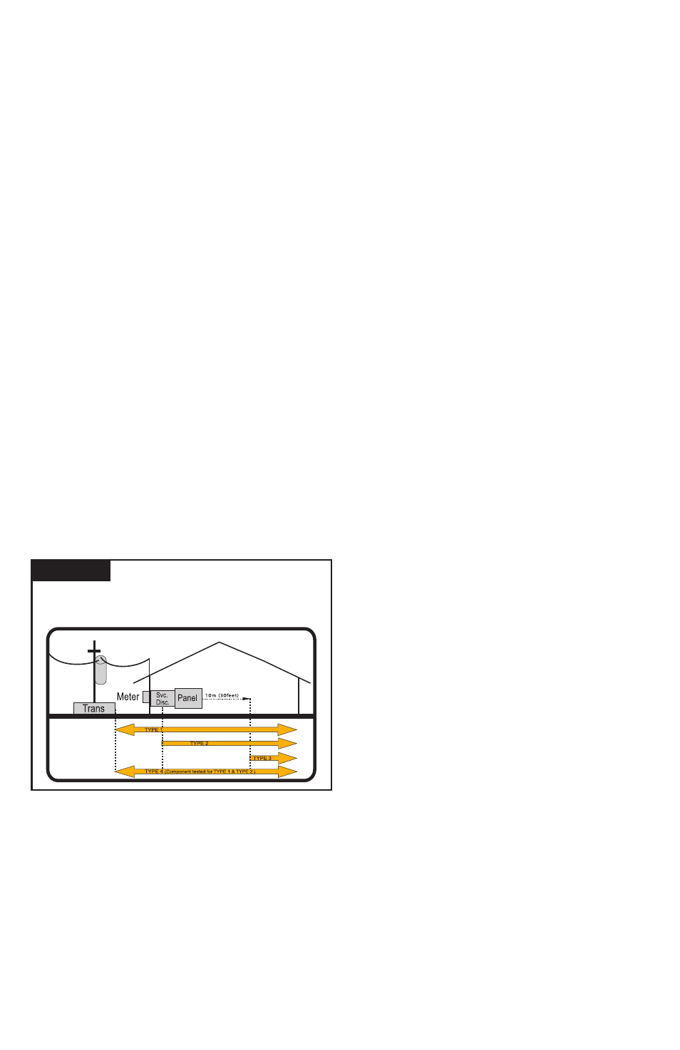
SPD Types: Types 1, 2, 3, & 4
Based on Location within electrical distribution system
(also coincides with ANSI/IEEE C62.41.2 - 2002 Categories C, B & A)
Figure 1
NEC
®
Article 285 & UL 1449-3