Xb h/w/d (in. / mm.) weight, Xr h/w/d (in. / mm.) weight, Xw h/w/d (in. / mm.) weight – Advanced Protection XRL User Manual
Page 4
4
Unpacking & Preliminary Inspection
Inspect the entire shipping container for damage or signs
of mishandling. Remove the packing materials and further
inspect the unit for any obvious shipping damages.
If any damage was found and is a result of shipping
or handling, immediately file a claim with the shipping
company and forward a copy to APT.
Storage Environment
This SPD should be stored in a clean, dry environment.
Storage temperature range is -40°C (-40°F) to +60°C
(+140°F). Avoid exposure to high condensation.
PRE-INSTALLATION & INSTALLATION PLANNING
Operating Environment
The standard unit uses a Type 1/12/3R/4 enclosure.
Non-metallic polycarbonate 4X, stainless steel and Type
1 flush-mount or pull box enclosures are available as
options. Before installing, ensure that your enclosure type
and application are appropriate per NEMA 250 with regard
to moisture, dirt, excessive dust, flammable materials or
atmospheres, corrosive vapors, etc. Please consult factory
if enclosure needs to be changed.
This SPD is designed in an ambient temperature range
of -40°C (-40°F) to +60°C (+140°F) with a relative
humidity of 0% to 95% (non-condensing). Excessive
temperature may inadvertently operate internal thermal
overtemperature protectors.
On rare occasions in high temperature climates, SPDs
inside clear cover polycabonate enclosures have
experienced internal temperatures exceeding 200°F
(94°C). We recommend positioning the unit so that the
clear front avoids direct summer sunlight by shading or
not facing west.
Line Side versus Load Side Installation
The XA & XB family SPDs are tested and qualified as
Type 1 SPDs per UL 1449 Third Edition and 2008 NEC
®
.
This SPD can be installed on the Line Side of the service
overcurrent device per 2008 NEC
®
Article 285. Type 1
SPDs may also be installed in Type 2 applications. As
a generalization, it is more practical to install as Type 2
on load side of main overcurrent device for maintenance
reasons. Such installations would be similar to traditional
TVSS installations. (Note: cUL models are Type 2 due to
different cUL criteria.)
XR and XW SPD modules are Type 4 components that
have been evaluated by UL for use in Type 1 applications.
(XR’s and XW’s are essentially XA’s without enclosures for
installation within host electrical equipment.)
There may be circumstances where Line Side installation
is desirable. Follow all applicable Code requirements for
Line Side installation. We generally recommend that the
SPD be installed with a disconnecting mechanism for
servicing purposes.
Tip: APT offers an optional Disconnect Switch that has been
UL evaluated as part of the SPD. This includes SCCR and
Line Side suitability. If you do not use the APT Disconnect
option, select a disconnect switch rated for line side (UL
98) having appropriate SCCR rating including any required
overcurrent protection. This may be more time consuming
and expensive than anticipated. The optional Disconnect
Switch is fully engineered and almost certainly easier, smaller
and less expensive. Please contact APT Technical Support
as appropriate.
Audible Noise
SPD background noise is negligible or non-existent, and
does not restrict the location of installation.
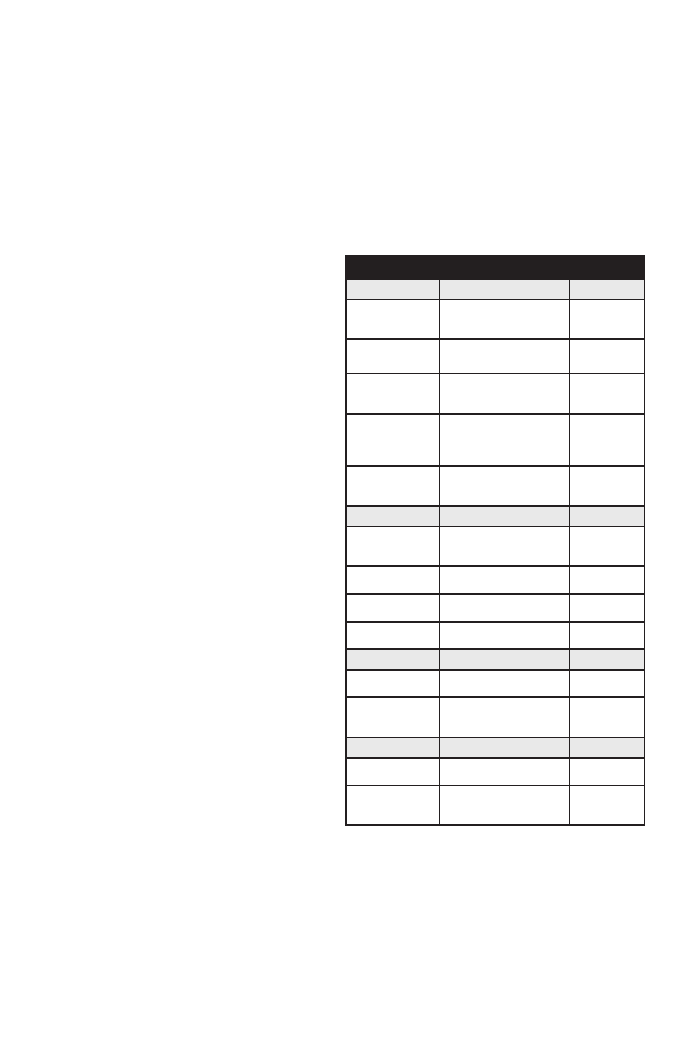
Mounting, Dimensions, and Weight
The XA & XB series include enclosures and are intended for
wall mounting. The XR & XW series are component SPDs
intended for installation within other electrical gear already
having enclosures. See Table 2. Mechanical drawings are
included in back of this manual (page 12).
TABLE 2: DIMENSIONS & WEIGHTS
XA
H/W/D (in. / mm.)
Weight
Standard (and w/
Opt. Disc. Switch
& <300kA)
12"x12"x6.5"
(305x305x165)
23 lbs
(10.4 kg)
With Opt. Disc.
Switch & >300kA
16"x14"x6.5"
(406x356x165)
32 lbs
(14.5 kg)
4X Non-Metallic
(std.)
(>300kA w/disc.)
14"x12"x7" (356x305x178)
16"x14"x7" (406x356x178)
14 lbs (6.4)
21 lbs (9.5)
4X Stainless
(>300kA w/disc.)
12"x12"x7.5"
(305x305x191)
16"x14"x7.5"
(406x356x191)
24 lbs (10.9)
33 lbs (15)
Pullbox & Flush
mount
(>300kA w/disc.)
12"x12"x6" (305x305x152)
16"x14"x6" (406x356x152)
21 lbs (9.5)
29 lbs (13.2)
XB
H/W/D (in. / mm.)
Weight
Standard
(includes Disc.
Switch)
20" x 20" x 7.5"
(508 x 508 x 191)
52 lbs
(23.6 kg)
4X Non-Metallic
24" x 24" x 8"
(610 x 610 x 203)
52 lbs
(23.6 kg)
4X Stainless
20" x 20" x 7.5"
(508 x 508 x 191)
53 lbs
(24 kg)
Pullbox & Flush
mount
20" x 20" x 6"
(508 x 508 x 152)
43 lbs
(19.5 kg)
XR
H/W/D (in. / mm.)
Weight
Standard
6.5" x 11" x 4.5"
(165 x 279 x 114)
5 lbs
(2.3 kg)
With Opt. Disc.
Switch on alum.
backplane
10.75" x 10.88" 4.5"
(273 x 276 x 114)
9 lbs
(4.1 kg)
XW
H/W/D (in. / mm.)
Weight
Standard
9" X 11" X 4.5"
(229 x 279 x 114)
7 lbs
(3.2 kg)
With Opt. Disc.
Switch on alum.
backplane
14.75" X 12.9" X 5.25"
(375 x 328 x 133)
11 lbs
(5 kg)
Service Clearance
Service clearance is needed at the front of the unit; 36
inches minimum is the required distance for clearance
pursuant to the NEC
®
.
Lead Lengths & Maximizing SPD Performance
SPDs must be located as close to the circuit as possible
to minimize parasitic losses. Surges are high current, high
frequency events that cause substantial voltage drops
across conductors. This hurts SPD performance. Use the
shortest & straightest possible leads. Pre-Plan installations