3 analog inputs, Analog inputs, 2 device description – West Control Solutions DataVU 5 User Manual
Page 14
2 Device description
14
Channel line
(channel
representation)
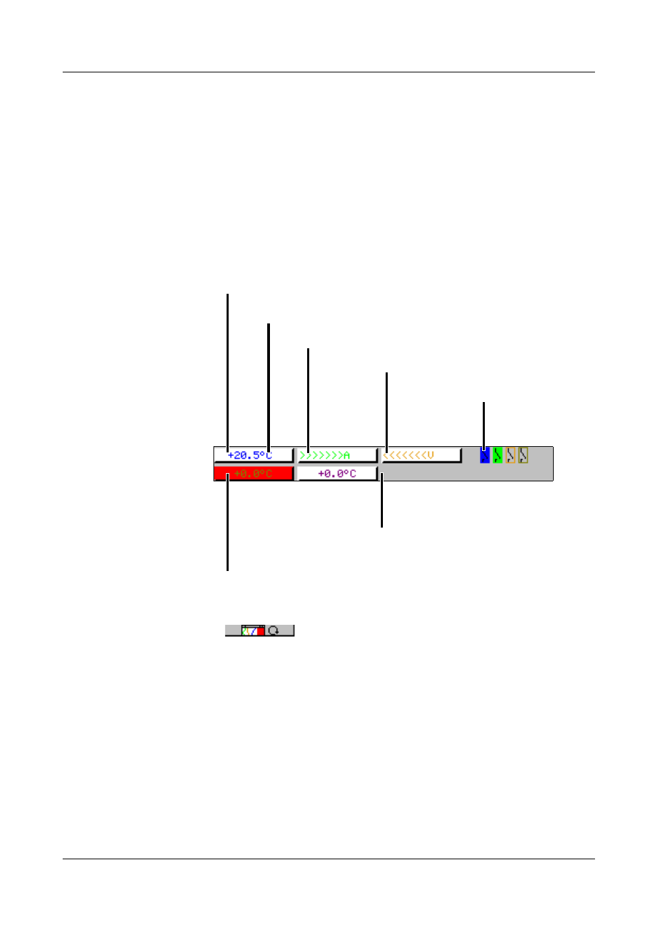
The channel line shows the measurements of the active channels and their unit
as
- a measurement
- scale or
- bar graph.
Alternatively, the header can be switched off altogether.
In addition, alarms and out-of-limit conditions are made directly visible,
depending on the display mode.
Example: Measurement (small meas.)
Selection and visual presentation of the channel line can be controlled through
the parameter Parameterization ➔ Diagram view ➔ Channel represent. or by
using the
key.
With the help of the parameter Parameterization ➔ Diagram view ➔ Channel
indication ➔ Channel 1 — 6, it is possible to suppress the display of individual
channels in the channel line. This is especially useful for scale or bar graph
display, where more space is needed to show the diagram. The channels that
have been suppressed in the display will nevertheless be recorded, and shown
on the diagram.
2.3 Analog inputs
Internal
analog inputs
The paperless recorder can be equipped with 3 or 6 analog inputs. When
configuring the analog inputs (Chapter 4.2 “Table of configuration
parameters”), these are designated as analog input 1 — 3 (1 — 6).
Numerical display
The measurements are shown in numerical form.
OFF
If a channel has been switched off, then
there will be no indication at all.
Unit of measurement
Alarm
If an alarm (e.g. out-of-limit) is present,
the measurement of the channel is shown on a red background.
Overrange
Underrange
(underrange)
State of the
event traces