9 module 9 - f, 3d-lev, 48 code 66 code – NOSHOK 2100 Series Field Upgradeable Dual Input Process Indicator User Manual
Page 30: Actory, Ervice, Perations, Parameter menu
30
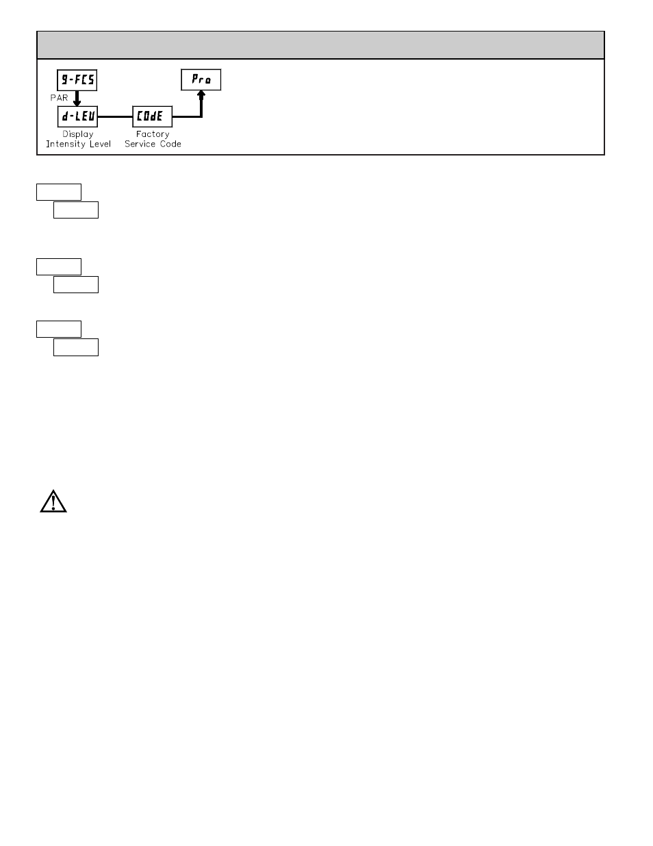
5.9 MODULE 9 - F
ACTORY
S
ERVICE
O
PERATIONS
(
9-FCS
)
PARAMETER MENU
Enter the desired Display Intensity Level (0-15) by
using the arrow keys. The display will actively dim or
brighten as the levels are changed. This parameter also
appears in Quick Programming Mode when enabled.
DISPLAY INTENSITY LEVEL
3
d-LEV
The meter has been fully calibrated at the factory.
Scaling to convert the input signal to a desired display
value is performed in Module 1. If the meter appears to be
indicating incorrectly or inaccurately, refer to
Troubleshooting before attempting to calibrate the meter.
When recalibration is required (generally every 2 years), it should only be
performed by qualified technicians using appropriate equipment. Calibration
does not change any user programmed parameters. However, it may affect the
accuracy of the input signal values previously stored using the Apply (
APLY
)
Scaling Style.
Calibration may be aborted by disconnecting power to the meter before
exiting Module 9. In this case, the existing calibration settings remain in effect.
CALIBRATION
48
COdE
66
COdE
RESTORE FACTORY DEFAULTS
Use the arrow keys to display
COdE 66
and press PAR.
The meter will display
rESEt
and then return to
COdE 50
.
Press DSP key to return to Display Mode. This will
overwrite all user settings with the factory settings.
ANALOG OUTPUT CARD CALIBRATION
Before starting, verify that the precision voltmeter (voltage output) or current
meter (current output) is connected and ready. Perform the following procedure:
1. Use the arrow keys to display
COdE 48
and press PAR.
2. Use the arrow keys to choose
OUt
and press PAR.
3. Using the chart below, step through the five selections to be calibrated. At
each prompt, use the arrow keys to adjust the external meter display to
match the selection being calibrated. When the external reading matches, or
if this range is not being calibrated, press PAR.
4. When
NO
appears remove the external meters and press PAR twice.
SELECTION
EXTERNAL METER
ACTION
0.0_A
0.00
Adjust if necessary, press PAR
4.0_A
4.00
Adjust if necessary, press PAR
20.0_A
20.00
Adjust if necessary, press PAR
0.0v
0.00
Adjust if necessary, press PAR
10.0v
10.00
Adjust if necessary, press PAR
WARNING: Calibration of this meter requires a signal source with an
accuracy of 0.01% or better and an external meter with an accuracy of
0.005% or better.
Before starting, verify that the Input Ranger Jumper is set for the range to be
calibrated. Also verify that the precision signal source is connected and ready.
Allow a 30 minute warm-up period before calibrating the meter.
NO
and PAR
can be chosen to exit the calibration mode without any changes taking place.
Then perform the following procedure:
1. Use the arrow keys to display (
COdE 48
) and press PAR.
2. Choose the input channel/range to be calibrated by using the arrow keys and
press PAR. (
NO
and PAR can be chosen to exit the calibration mode without
any changes taking place.)
3. When the zero range limit appears on the display, apply the appropriate:
- Voltage range: dead short applied
- Current range: open circuit
4. Press PAR and the top range limit will appear on the display after
approximately 1 second.
5. With the top range limit on the display, apply the appropriate:
- Voltage range: 10 VDC
- Current range: 20 mADC
6. Press PAR and
CAL
.
NO
will appear on the display after approximately 1
second.
7. When
NO
appears, press PAR twice.
8. If the meter is not field scaled, then the input display should match the value
of the input signal.
9. Repeat the above procedure for each input range to be calibrated.
INPUT CALIBRATION