NOSHOK 2100 Series Field Upgradeable Dual Input Process Indicator User Manual
Page 25
25
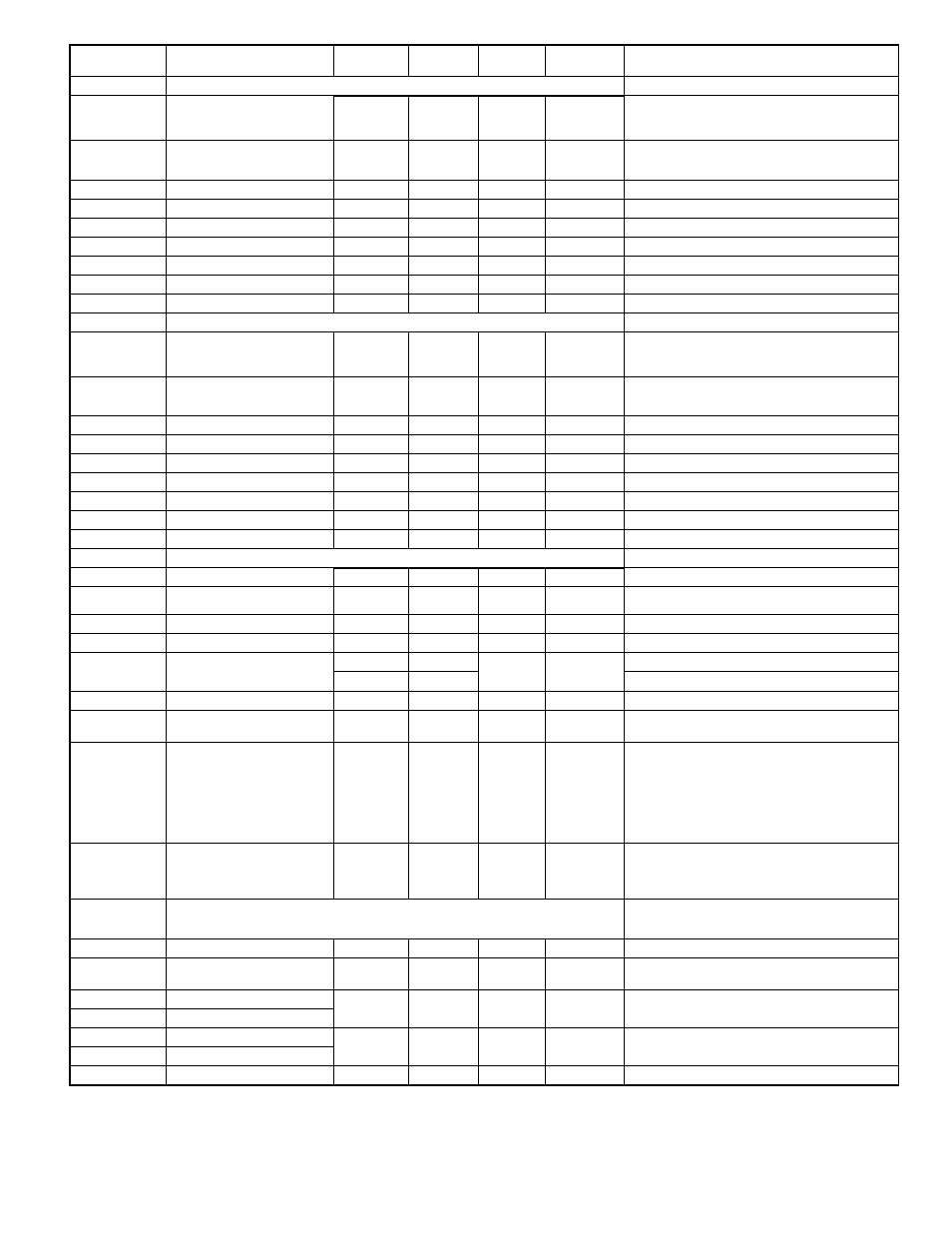
REGISTER
ADDRESS
1
REGISTER NAME
LOW LIMIT
2
HIGH LIMIT
2
FACTORY
SETTING
ACCESS
COMMENTS
40406
40396
40386
40412
40402
40392
40382
Transmit Delay
Output Logic
Output Logic
Assignment
Baud Rate
Action
Action
0
0
0
0
0
0
0
250
1
1
8
7
10
10
10
0
0
0
7
0
0
Read/Write
Read/Write
Read/Write
Read/Write
Read/Write
Read/Write
1=0.001 Second
0=Normal, 1=Reverse
0=Normal, 1=Reverse
0=NONE, 1=A-REL, 2=A-AbS, 3=b-rEL, 4=b-AbS,
5=CALC, 6=tot, 7=HI, 8=LO
0=300, 1=600, 2=1200, 3=2400, 4=4.8k, 5=9.6k,
6=19.2k, 7=38.4k
0=No, 1=Ab-HI, 2=Ab-Lo, 3=AU-HI, 4=AU-LO, 5=dE-HI,
6=dE-LO, 7=bANd, 8=bNdIn, 9=totLo, 10=totHI
0=No, 1=Ab-HI, 2=Ab-Lo, 3=AU-HI, 4=AU-LO, 9=totLo,
10=totHI; Do not use 5-8.
40411
40401
40391
40381
Type
Type
Assignment
Assignment
0
0
0
0
2
2
6
6
1
2
0
0
Read/Write
Read/Write
Read/Write
Read/Write
0 = 0-20 mA, 1 = 4-20 mA, 2 = 0-10 V
0=RLC Protocol, 1=Modbus RTU, 2=Modbus ASCII
ANALOG OUTPUT PARAMETERS
SERIAL COMMUNICATIONS PARAMETERS
SETPOINT 4 OUTPUT PARAMETERS
SETPOINT 3 OUTPUT PARAMETERS
40409
40399
40389
40405
40395
40385
Load Serial Settings
Lit - Annunciator
Lit - Annunciator
Address
Off Delay
Off Delay
0
0
0
1
0
0
0
1
3
3
247
99
32750
32750
0
1
1
247
0
0
Read/Write
Read/Write
Read/Write
Read/Write
Read/Write
Read/Write
Read/Write
0=Off, 1=Normal, 2=Reverse, 3=Flash
0=Off, 1=Normal, 2=Reverse, 3=Flash
Modbus: 1-247
RLC Protocol: 0-99
1=0.1 Second
1=0.1 Second
40408
40398
40388
40416
40414
40404
40394
40384
Print Options
Standby
Standby
Analog High Value (Lo word)
Analog Low Value (Lo word)
Parity
On Delay
On Delay
0
0
0
0
0
0
63
1
1
2
32750
32750
0
0
0
0
0
0
Read/Write
Read/Write
Read/Write
Read/Write
Read/Write
Read/Write
0=No, 1 = Yes
0=No, 1 = Yes
0=None, 1=Even, 2=Odd
1=0.1 Second
1=0.1 Second
40417
40407
40397
40387
40415
40413
40403
40393
40383
Reset
Reset
Analog High Value (Hi word)
Analog Low Value (Hi word)
Data Bits
Hysteresis
Hysteresis
SEE MODULE 7 FOR DESCRIPTION OF PARAMETERS
0
0
0
0
-19999
-19999
0
1
1
100
1
2
2
99999
99999
1
65000
65000
0
0
0
10000
0
1
2
2
Read/Write
Read/Write
Read/Write
Read/Write
Read/Write
Read/Write
Read/Write
Read/Write
Read/Write
0=Max update rate, 1=0.1 second
0=No, 1=Yes
Not used when communications type is Modbus
0=Auto, 1=Latch1, 2=Latch2
0=Auto, 1=Latch1, 2=Latch2
0=7 bits, 1=8 bits
1=1 Display Unit
1=1 Display Unit
6=Tot
5=Calc
4=bAbs
3=b-Rel
2=A-Abs
1=A-Rel
0=None
6=Tot
5=Calc
4=bAbs
3=b-Rel
2=A-Abs
1=A-Rel
0=None
Update Time
Abbreviated Transmission (RLC
only)
0=No, 1=Yes
Not used when communications type is Modbus
Bit 0 - Print Input A Value
Bit 1 - Print Input B Value
Bit 2 - Print CALC Value
Bit 3 - Print Max & Min Values
Bit 4 - Print Total Value
Bit 5 - Print Setpoint Values
Changing 40401-40406 will not update until
this register is written with a 1. After the write, the
communicating device must be changed to the new
settings and the register returns to 0.
SEE MODULE 8 FOR DESCRIPTION OF PARAMETERS
(APPLIES ONLY WHEN LINEAR OUTPUT CARD,
IS INSTALLED)
Display value that corresponds with 10 V or
20 mA output
Display value that corresponds with 0 V, 0 mA or
4 mA output
1
For Input Registers, replace the 4xxxx with a 3xxxx in the above register address. The 3xxxx are a mirror of the 4xxxx Holding Registers.
2
An attempt to exceed a limit will set the register to its high or low limit value.