0 hi-t, 0 lo-t, Off b-lit – NOSHOK 2100 Series Field Upgradeable Dual Input Process Indicator User Manual
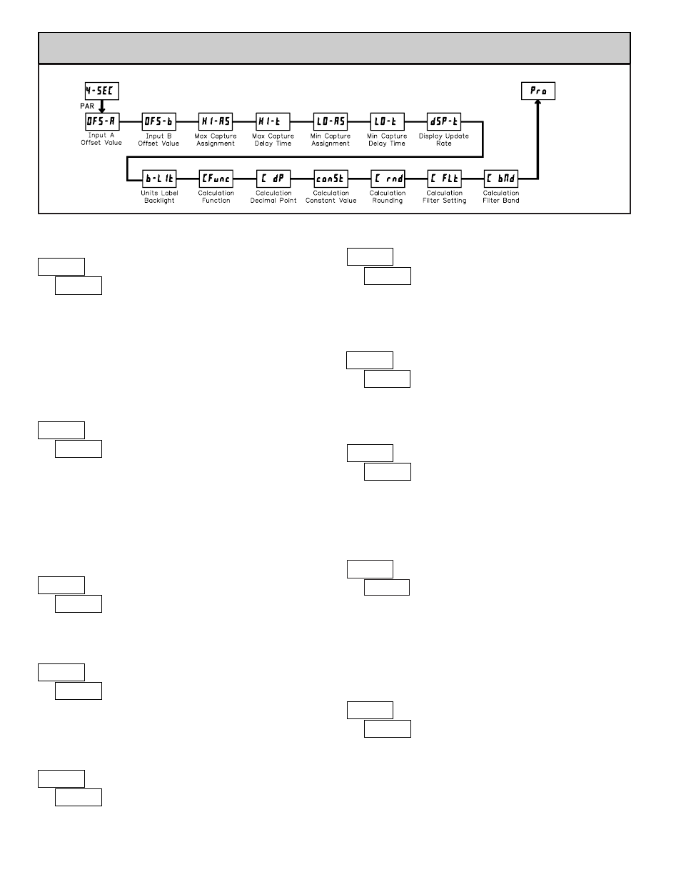
Page 16: 000 ofs-a, 1dsp-t, 4 module 4 - s, 000 ofs-b, A-rel hi-as, A-rel l0-as, 000 c dp
16
1.0
HI-t
MAX CAPTURE DELAY TIME
When the Input Display is above the present MAX value for the entered
delay time, the meter will capture that display value as the new MAX reading.
A delay time helps to avoid false captures of sudden short spikes.
1.0
LO-t
MIN CAPTURE DELAY TIME
When the Input Display is below the present MIN value for the entered delay
time, the meter will capture that display value as the new MIN reading. A delay
time helps to avoid false captures of sudden short spikes.
OFF
b-LIt
UNITS LABEL BACKLIGHT
The Units Label Kit Accessory contains a sheet of custom unit overlays
which can be installed in to the meter’s bezel display assembly. The backlight
for these custom units is activated by this parameter.
0.000
OFS-A
INPUT A OFFSET VALUE*
Unless a Zero Display was performed or an offset from Module 1 scaling is
desired for Input A, this parameter can be skipped. The Display Offset Value is
the difference between the Absolute (gross) Display value and the Relative (net)
Display value for the same input level. The meter will automatically update this
Display Offset Value after each Zero Display. The Display Offset Value can be
directly keyed-in to intentionally add or remove display offset. See Relative /
Absolute Display and Zero Display explanations in Module 2.
1
dSP-t
DISPLAY UPDATE RATE
This parameter determines the rate of display update.
5.4 MODULE 4 - S
ECONDARY
F
UNCTION
P
ARAMETERS
(
4-SEC
)
PARAMETER MENU
0.0
to
3275.0
sec.
0.0
to
3275.0
sec.
-19999
to
19999
1
2
5
10
OFF
ON
20
updates/sec.
0.000
OFS-b
INPUT B OFFSET VALUE*
Unless a Zero Display was performed or an offset from Module 1 scaling is
desired for Input B, this parameter can be skipped. The Display Offset Value is
the difference between the Absolute (gross) Display value and the Relative (net)
Display value for the same input level. The meter will automatically update this
Display Offset Value after each Zero Display. The Display Offset Value can be
directly keyed-in to intentionally add or remove display offset. See Relative /
Absolute Display and Zero Display explanations in Module 2.
-19999
to
19999
A-rEL
HI-AS
MAX CAPTURE ASSIGNMENT
Select the desired parameter that will be assigned to the Max Capture.
CALC
b-Abs
b-rEL
A-Abs
A-rEL
A-rEL
L0-AS
MIN CAPTURE ASSIGNMENT
Select the desired parameter that will be assigned to the Min Capture.
CALC
b-Abs
b-rEL
A-Abs
A-rEL
0.000
C dp
CALCULATION DECIMAL POINT
This parameter determines the decimal point location for the Calculation
Display.
c+a+b
Cfunc
CALCULATION FUNCTION
This parameter determines the math calculation that will be performed on Input
A and Input B and shown on the calculation display. The above formulas
represent the available calculations;
A
= Input A relative value,
b
= Input B
relative value, and
c
= Calculation Constant Value (
conSt
). The Input A & B
decimal point locations do not affect the math function.
c+A+b c-A-b c+A-b ab/c cA/b
0.0000
0.000
0.00
0.0
0
*
The decimal point position will follow that selected in the “Display
Decimal Point” parameter.
c(1-A/B)