Serial rlc protocol communications, Sending serial commands and data, Type – NOSHOK 2100 Series Field Upgradeable Dual Input Process Indicator User Manual
Page 26: Command chart command string construction
26
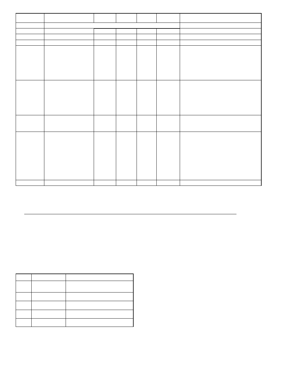
REGISTER
ADDRESS
1
REGISTER NAME
LOW LIMIT
2
HIGH LIMIT
2
FACTORY
SETTING
ACCESS
COMMENTS
40506
40502
Total & Calculation Error
Factory Service Data Register
N/A
N/A
N/A
N/A
N/A
N/A
Read Only
Read/Write
Factory Use Only - Do Not Modify
40501
Factory Service Register
N/A
N/A
N/A
Read/Write
Factory Use Only - Do Not Modify
FACTORY SERVICE
41101-41116
GUID/Scratch
N/A
40505
N/A
Input A/B Error
N/A
N/A
Read/Write
N/A
Reserved (may be used in future RLC software)
41001-41010
N/A
Slave ID
N/A
Read Only
N/A
N/A
Read Only
40504
Power Up Errors
N/A
N/A
N/A
Read Only
40503
Main Display Number
0
3
1
Read/Write
0=Display_, 1=Display A, 2=Display B, 3=Display C
Bit Cleared = No Error, Bit Set = Error
Bit 0 = Input A Hardware Error (ErInA)
Bit 1 = Input B Hardware Error (ErInb)
Bit 2 = Key Stuck at power-up Error (ErKEY)
Bit 3 = Power Down Data Checksum Error (EEPdn)
Bit 4 = Parameter Checksum Error (EEPar)
Bit 5 = Calibration Data Checksum error (EECal)
Bit 6 = Linear Output Card Calibration Checksum Data
Error (EELin)
Bit Cleared = No Error, Bit Set = Error
Bit 0 = Input A Display Underflow (<-19999)
Bit 1 = Input A Display Overflow (>99999)
Bit 2 = Input A Signal Underrange (<13 V or <-26 mA)
Bit 3 = Input A Signal Overrange (>13 V or >26 mA)
Bit 4 = Input A Display Underflow (<-19999)
Bit 5 = Input A Display Overflow (>99999)
Bit 6 = Input A Signal Underrange (<13 V or <-26 mA)
Bit 7 = Input A Signal Overrange (>13 V or >26 mA)
Bit 0 = Calculation Display Underflow (<-19999)
Bit 1 = Calculation Display Overflow (>99999)
Bit 4 = Total Value Display Underflow (<-99999900)
Bit 5 = Total Value Display Overflow (>999999000)
RLC-2100 a b <0100h><20h><20h><10h>
| | | | | \_16 Scratch
| | | | \_32 Reads
| | | \_32 Writes
| | \_Version Number
| \_b=Linear Card “0”=None,
| “1”=Yes
\_ a = SP Card, “0”-No SP, “2”
or “4” SP
(a = “0”, “2”, “4” SP card installed; b = “0” or “1” Linear
Card installed), 1.00 version (or higher)32 reads, 32
writes 16 scratch
1
For Input Registers, replace the 4xxxx with a 3xxxx in the above register address. The 3xxxx are a mirror of the 4xxxx Holding Registers.
2
An attempt to exceed a limit will set the register to its high or low limit value.
SERIAL RLC PROTOCOL COMMUNICATIONS
RLC Communications requires the Serial Communications Type Parameter
(
tYPE
) be set to
rLC
.
SENDING SERIAL COMMANDS AND DATA
When sending commands to the meter, a string containing at least one
command character must be constructed. A command string consists of a
command character, a value identifier, numerical data (if writing data to the
meter) followed by a the command terminator character * or $.
Command Chart
Command String Construction
The command string must be constructed in a specific sequence. The meter
does not respond with an error message to invalid commands. The following
procedure details construction of a command string:
1. The first characters consist of the Node Address Specifier (N) followed by a
1 or 2 character address number. The address number of the meter is
programmable. If the node address is 0, this command and the node address
itself may be omitted. This is the only command that may be used in
conjunction with other commands.
2. After the address specifier, the next character is the command character.
3. The next character is the Register ID. This identifies the register that the
command affects. The P command does not require a Register ID character.
It prints according to the selections made in print options.
4. If constructing a value change command (writing data), the numeric data is
sent next.
5. All command strings must be terminated with the string termination
characters * or $. The meter does not begin processing the command string
until this character is received. See Timing Diagram figure for differences
between terminating characters.
Initiates a block print output. Registers are
defined in programming.
Block Print Request
(read)
P
Reset a register or output. Must be followed
by register ID character
Reset
R
Write to register of the meter. Must be followed
by register ID character and numeric data.
Value change (write)
V
Read a register from the meter. Must be
followed by register ID character.
Transmit Value (read)
T
Address a specific meter. Must be followed by
a one or two digit node address. Not required
when address = 0.
Node (Meter) Address
Specifier
N
Notes
Description
Command