55rl, 8data, No par – NOSHOK 2100 Series Field Upgradeable Dual Input Process Indicator User Manual
Page 20: 247 addr, 7 module 7 - s, Mbas type 0.010 delay
20
38400
bAUd
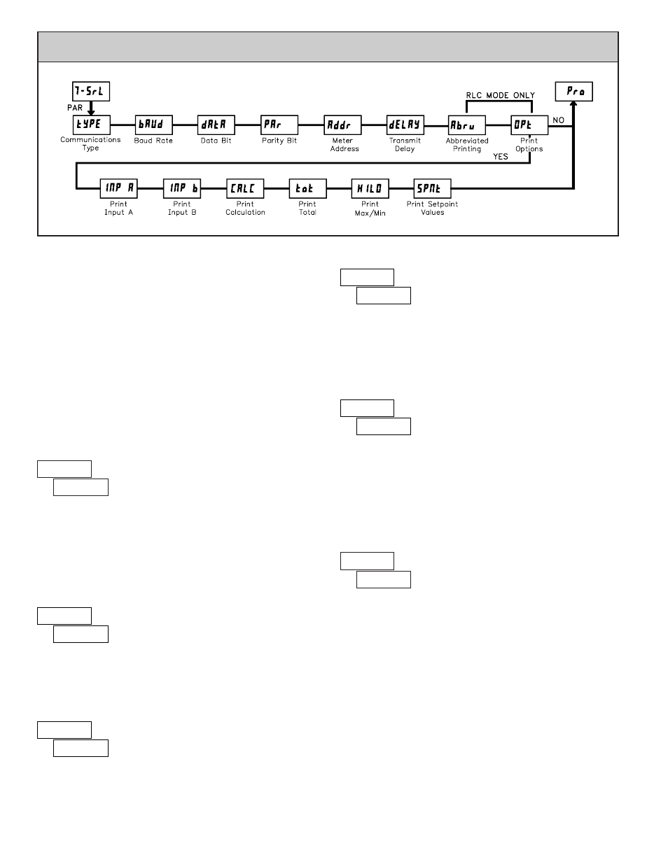
BAUD RATE
Set the baud rate to match the other serial communications equipment on the
serial link. Normally, the baud rate is set to the highest value that all the serial
equipment are capable of transmitting and receiving.
8
dAtA
DATA BIT
Select either 7 or 8 bit data word lengths. Set the word length to match the
other serial communications equipment on the serial link.
NO
PAr
PARITY BIT
Set the parity bit to match that of the other serial communications equipment
on the serial link. The meter ignores the parity when receiving data and sets the
parity bit for outgoing data. If no parity is selected with 7 bit word length, an
additional stop bit is used to force the frame size to 10 bits.
247
Addr
METER UNIT ADDRESS
Enter the serial meter (node) address. The address range is dependent on the
tYPE
parameter. With a single unit, configured for RLC protocol (
tYPE
=
rLC
), an address is not needed and a value of zero can be used. With multiple
units (RS485 applications), a unique 2 digit address number must be assigned
to each meter.
PARAMETER MENU
4800 9600
300
600
1200
19200 38400
2400
7
8
NO
Odd
EVEN
00
to
99 (
(RLC Protocol)
1
to
247
(Modbus)
5.7 MODULE 7 - S
ERIAL
C
OMMUNICATIONS
P
ARAMETERS
(
7-55rL
)
Module 7 is the programming module for the Serial Communications
Parameters. These parameters are used to match the serial settings of the
2100 with those of the host computer or other serial device, such as a
terminal or printer. This programming module can only be accessed if an RS232
or RS485 Serial Communications card is installed.
This section also includes an explanation of the commands and formatting
required for communicating with the 2100. In order to establish serial
communications, the user must have host software that can send and receive
ASCII characters or utilizes Modbus protocol. For serial hardware and wiring
details, refer to section 3.6 Serial Communication Wiring.
This section replaces the bulletin shipped with the RS232 and RS485 serial
communications plug-in cards. Discard the separate bulletin when using those
serial plug-in cards with the 2100. Also, this section does NOT apply to the
DeviceNet, or Profibus-DP communication cards. For details on the operation
of the Fieldbus cards, refer to the bulletin shipped with each card.
Select the desired communications protocol. Modbus is preferred as it
provides access to all meter values and parameters. Since the Modbus protocol
is included within the 2100, the
Modbus option card, should not be used
The RS485 or RS232 card should be used instead.
COMMUNICATIONS TYPE
rLC
- RLC Protocol
Mbrt
- Modbus RTU
MbAS
- Modbus ASCII
MbAS
tyPE
0.010
dELAy
TRANSMIT DELAY
Following a transmit value (‘*’ terminator) or Modbus command, the
2100 will wait this minimum amount of time in seconds before issuing a
serial response.
0.010
to
0.250