1 module 1 - s, 8 rate, Volt range – NOSHOK 2100 Series Field Upgradeable Dual Input Process Indicator User Manual
Page 11: 000 decpt, 001 round, 0 filtr, 010 band, 2pts, Key style, Ignal
11
5.1 MODULE 1 - S
IGNAL
I
NPUT
P
ARAMETERS
19.8
rAtE
ADC CONVERSION RATE
Select the ADC conversion rate. The selection does not affect the display
update rate, (however it does affect setpoint response time). The default factory
setting of 19.8 is recommended for most applications. Selecting a fast update
rate may cause the display to appear very unstable.
105
19.8
16.7
30
20
7.5
5.3
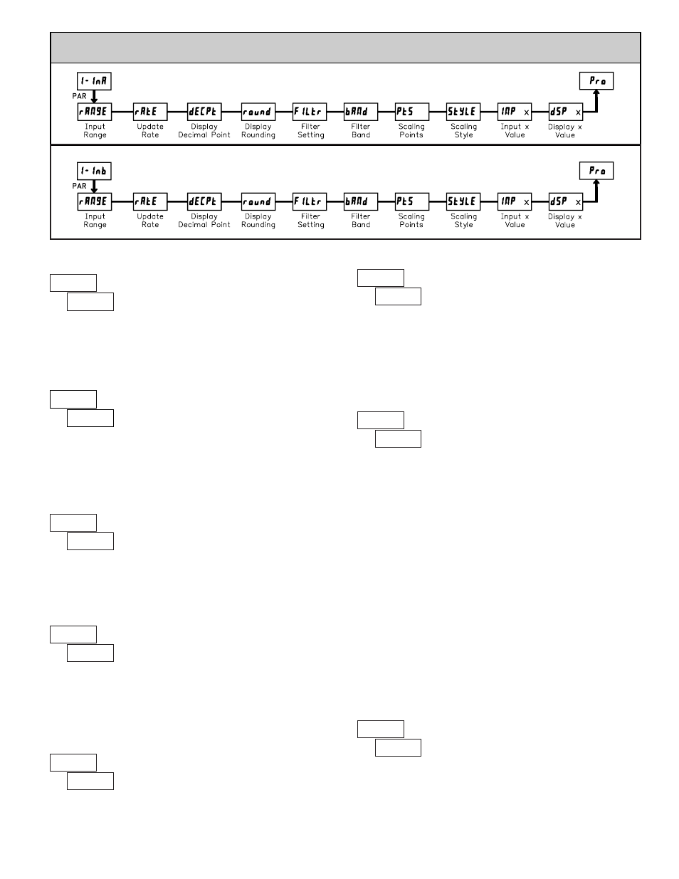
INPUT A PARAMETER MENU
INPUT B PARAMETER MENU
VoLt
rANgE
INPUT RANGE
Select the input range that corresponds to the external signal. Before
applying signal configure input jumper to match setting desired.
20.000 mA
±10.000 V
10.000 V
C-Sqr
curr
V-Sqr
VoLt
RANGE
RESOLUTION
SELECTION
0.000
dECPt
0.000 0.0000
0.00
0.0
0
DISPLAY DECIMAL POINT
Select the decimal point location for the Input display. (The TOT display
decimal point is a separate parameter.) This selection also affects
round
,
dSP1
and
dSP2
parameters and setpoint values.
0.001
round
DISPLAY ROUNDING*
10
100
50
20
5
2
1
Rounding selections other than one, cause the Input Display to ‘round’ to the
nearest rounding increment selected (ie. rounding of ‘5’ causes 121 to round to
120 and 124 to round to 125). Rounding starts at the least significant digit of
the Input Display. Remaining parameter entries (scaling point values, setpoint
values, etc.) are not automatically adjusted to this display rounding selection.
1.0
FILtr
FILTER SETTING
The input filter setting is a time constant expressed in tenths of a second. The
filter settles to 99% of the final display value within approximately 3 time
constants. This is an Adaptive Digital Filter which is designed to steady the
Input Display reading. A value of ‘0’ disables filtering.
0.0
to
25.0
seconds
0.010
bANd
FILTER BAND*
The digital filter will adapt to variations in the input signal. When the
variation exceeds the input filter band value, the digital filter disengages. When
the variation becomes less than the band value, the filter engages again. This
allows for a stable readout, but permits the display to settle rapidly after a large
process change. The value of the band is in display units, independent of the
Display Decimal Point position. A band setting of ‘0’ keeps the digital filter
permanently engaged.
0
to
250
display units
2
PtS
SCALING POINTS
Linear - Scaling Points (2)
For linear processes, only 2 scaling points are necessary. It is recommended
that the 2 scaling points be at opposite ends of the input signal being applied.
The points do not have to be the signal limits. Display scaling will be linear
between and continue past the entered points up to the limits of the Input Signal
Jumper position. Each scaling point has a coordinate-pair of Input Value (
INP
)
and an associated desired Display Value (
dSP
).
Square Root Extraction Input Range - Scaling Points (2)
The 2100 can apply the square root function directly to the sensor signal
by selecting the Square Root Extraction Input Range (
U-Sqr
or
C-Sqr
). When
configured for Square Root Extraction, piecewise multipoint linearization is not
required and only the first 2 scaling points are used. For proper operation the
Display 1 (
dSP 1
) value must be zero.
Nonlinear - Scaling Points (Greater than 2)
For non-linear processes, up to 16 scaling points may be used to provide a
piece-wise linear approximation. (The greater the number of scaling points
used, the greater the conformity accuracy.) The Input Display will be linear
between scaling points that are sequential in program order. Each scaling point
has a coordinate-pair of Input Value (
INP
) and an associated desired Display
Value (
dSP
). Data from tables or equations, or empirical data could be used to
derive the required number of segments and data values for the coordinate pairs.
2
to
16
*
The decimal point position is dependent on the selection made in the
“Display Decimal Point” parameter.
KEY
StYLE
SCALING STYLE
If Input Values and corresponding Display Values are known, the Key-in
(
KEY
) scaling style can be used. This allows scaling without the presence or
changing of the input signal. If Input Values have to be derived from the actual
input signal source or simulator, the Apply (
APLY
) scaling style must be used.
apply signal
APLY
key-in data
KEY
±20.000 mA