Part a system installation and start-up – KROHNE UFM 500 EN User Manual
Page 5
5
Part A
System installation and start-up
1.
Installation in the pipeline
1.1
Preliminary information
1. Location and position as required, but sensor axis
must be approximately horizontal if flowmeter is in-
stalled in slightly ascending or horizontal pipe runs.
2. Hard-to-reach locations
Where UFM 400 K and UFM 500 K compact flow-
meters have not been ordered and supplied in accor-
dance with Versions 1 to 10 (see sect. 8.6), the
configuration can be changed subsequently:
•
Turn the indicating circuit board through
±
90
°
or
180
°
to obtain horizontal positioning of the display
(see sect. 8.4)
•
Turn signal converter housing through
±
90
°
(see
sect. 8.5)
3. Measuring tube must be completely filled at all
times.
4. Flow direction +/-: note arrows on flowmeter and
also fct. 3.1.7 (refer to sections 4.3 and 5.4).
5. Bolts and nuts: to install make sure there is
sufficient room next to the pipe flanges.
6. Vibration: support the pipeline on both sides of the
flowmeter.
7. Large meter sizes, DN>200 (8”): use adapter pipes
to permit axial shifting of counter flanges to facilitate
installation.
8. Inlet and outlet sections
(DN = meter size)
Inlet section
single beam
double beam
−
Downstream of
pump
50
×
DN
15
×
DN
−
Downstream of fully
opened control valve
50
×
DN
10
×
DN
−
Downstream of 2
quarter bends on
different levels
40
×
DN
10
×
DN
−
Downstream of 2
quarter bends on one
level
25
×
DN
10
×
DN
−
Downstream of 1
quarter bend
20
×
DN
10
×
DN
−
Downstream of
reducer (
α
/2 = 7
°
)
15
×
DN
no additional
inlet section
−
Outlet section
5
×
DN
5
×
DN
9. Vortex or corkscrew flow: increase inlet and outlet
sections or install flow straighteners.
10. Zero setting is normally not necessary, but it can be
checked under flowing conditions as outlined in sect 7.2.
Shutoff valves should therefore be provided upstream
and/or downstream of the primary head unless the pipe
configuration already rules out the possibility of the
primary head being drained of fluid. (For zero check see
section 7.2).
11. Mixing different fluid products. Install the
flowmeter upstream of mixing point or at an
adequate distance downstream, minimum
distance 30x DN (DN = meter size), otherwise
output/display may be unsteady.
12. Ambient temperature:
product temperature
≤
60
°
C/140
°
F
all systems: -25 to +60
°
C/ -13 to +140
°
F
product temperature > 60
°
C/140
°
F
compact systems: -25 to +40
°
C/ -13 to +104
°
F
separate systems: -25 to +60
°
C/ -13 to +140
°
F
13. Pipeline along a wall: where possible, the distance
between pipe centerline and wall must be more than
0.5 m (1.6 ft) for the UFM 400 K and UFM 500 K
flowmeters. If less, first connect all cables to the
terminals in the terminal compartment (power supply
and outputs), and install an intermediate connection
box before installing flowmeter in pipeline.
14. Insulated pipeline: do not insulate UFM 400 K and
UFM 500 K compact flowmeters.
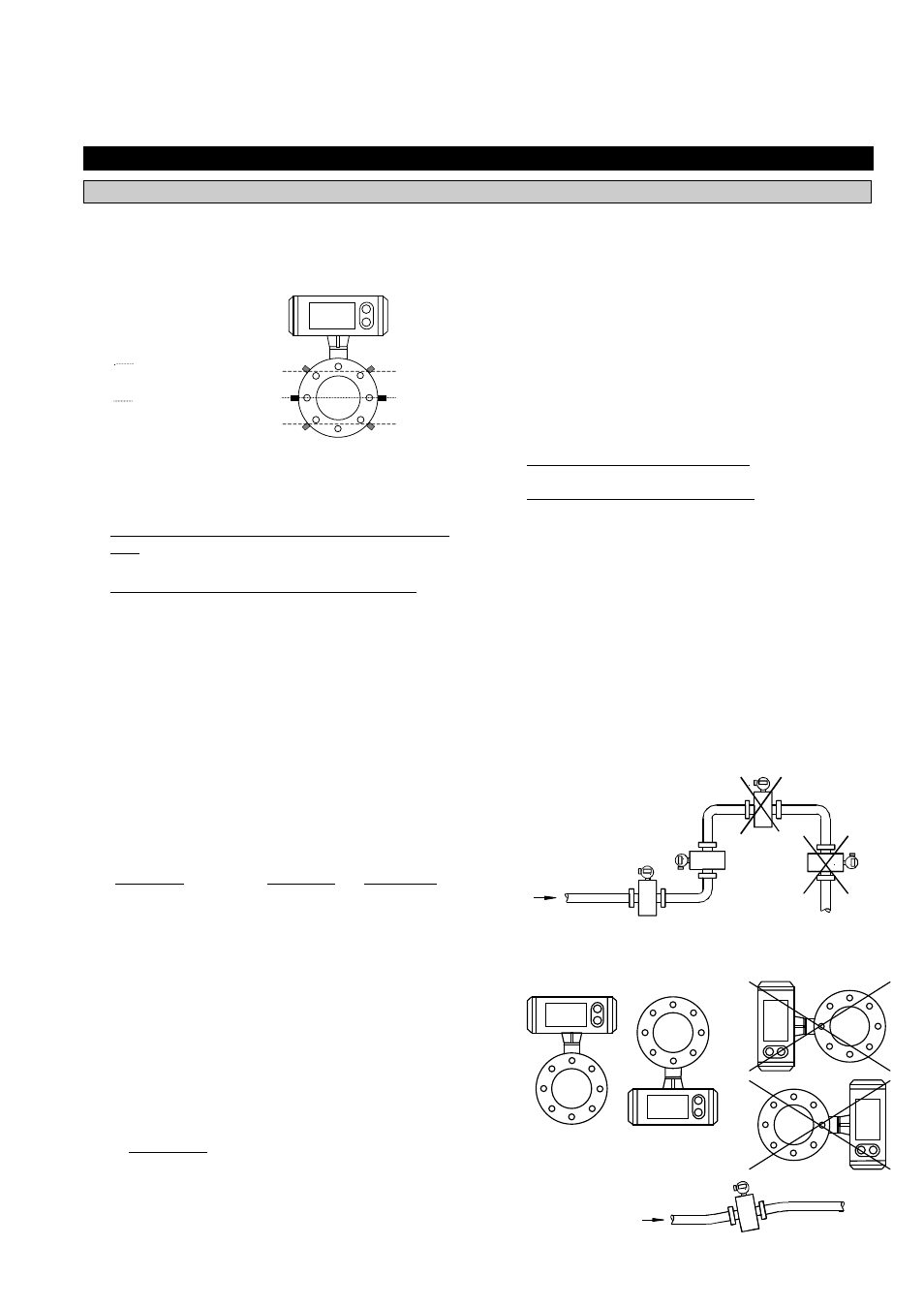
15. Suggestions for installation
To avoid measuring errors due to air inclusion, please
observe the following:
Sensor axis
(2 beams)
Sensor axis
(1 beam)
Highest point of pipe run
(Air bubbles that are collected in
the
measuring tube cause faulty
measurements).
Preferred
Locations
Downpipe
“ Zero“ flow
Velocity.
Lined drained.
Faulty
measurements
Open
discharge
.
Horizontal pipe run
Install in slightly ascending pipe section.
If not possible, ensure adequate
velocity
to prevent air, gas or vapor from
Horizontal and slightly ascending pipelines
Always install signal converter (and
terminal box) on the top or underside of
the pipe,