KROHNE UFM 500 EN User Manual
Page 49
49
12.
Block diagrams
12.1
Signal converter UFC 400 ...
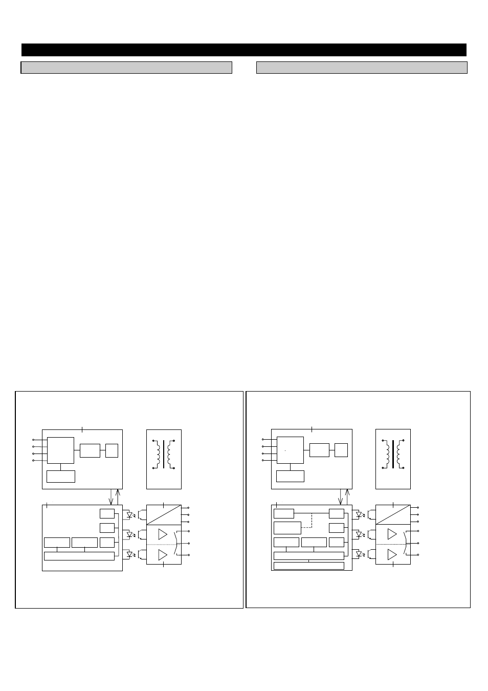
Signal converter UFC 400
The UFC 400 consists of four functional groups.
Functional group 1 generates the ultrasonic waves, controls
the sensors and carries out high-precision measurement of the
propagation time.
In functional group 2 the digitized data supplied by
µ
P 01
are evaluated by microprocessor
µ
P 02 in accordance with the
functions, operating and primary head data which are factory
set. With the aid of the KROHNE-developed LSI circuit
(KSA), microprocessor
µ
P 02 controls the outputs that are
galvanically isolated by opto-couplers (functional groups 3
and 4).
The KSA module is also used to feed last counts to the
EEPROM. In the event of a power failure, last counts are
saved in EEPROM 2. In the same way as operating and
functional check data are permanently stored in EEPROM 1,
both are retained for 10 years without auxiliary power.
Functional group 3 converts an output signal into a
proportional current. This group is galvanically isolated from
the other groups.
Functional group 4 consists of power drivers to allow control
of electronic (EMC) or electromechanical (EC) totalizers and
indicators. The group is galvanically isolated from the other
groups. Note that the pulse output and the status output share
the same common.
12.2
Signal converter UFC 500 ...
Signal converter UFC 500
The UFC 500 consists of four functional groups.
Functional group 1 generates the ultrasonic waves, controls
the sensors and carries out high-precision measurement of the
propagation time.
In functional group 2 the digitized data supplied by
µ
P 01
are evaluated by microprocessor
µ
P 02 in accordance with the
functions, operating and primary head data set by way of the
3 keys. With the aid of the KROHNE-developed LSI circuit
(KSA), microprocessor
µ
P 02 controls the outputs that are
galvanically isolated by opto-couplers (functional groups 3
and 4). The last measured value and other information are
forwarded via this circuit to the alphanumeric LCD for
indication.
The KSA module is also used to feed last counts to the
EEPROM. In the event of a power failure, last counts are
saved in EEPROM. In the same way as operating and
functional data are permanently stored in EEPROM 1, both
are retained for 10 years without auxiliary power.
Functional group 3 converts an output signal into a
proportional current. This group is galvanically isolated from
the other groups.
Functional group 4 consists of power drivers to allow control
of electronic (EMC) or electromechanical (EC) totalizers and
indicators. The group is galvanically isolated from the other
groups. Note that the pulse output and the status output share
the same common.
Block diagram UFC 400...
Serial data
µ
P1
Count
Multiplex
er
and
Transmitt
Sensor
1
2
3
4
1
2
µ
P2
RA
RO
KSA
EEPROM
EEPROM
Current
output
0 (4) TO 20
mA
Pulse output
≤
1 kHz
EC/EMC
B1
B
-
B2
I+
I
I
-
Power
PW
3
I
4
Block diagram UFC 500...
Serial data
µ
P1
Count
Multiplex
er
and
Transmitt
Sensor
1
2
3
4
1
2
µ
P2
RA
RO
KSA
EEPROM
2
EEPROM
1
Current
output
0 (4) TO 20
mA
Pulse output
≤
1 kHz
EC/EMC
B1
B
-
B2
I+
I
I
-
Power
PW
3
I
4
3
3
magneti
c
Alpha numeric LC-