KROHNE UFM 500 EN User Manual
Page 37
37
8.
Service
8.1
Replacement of electronic unit of signal
converter
Replacement of electronic units
The electronic unit UFC 400/S can be used as replace-
ment unit for the following signal converters:
UFC 400 K (UFM 400 K compact flowmeters)
UFC 400 F (F = field housing, separate system)
The UFC 500 S electronic unit can be used as a replace-
ment unit for the following signal converters:
UFC 500 K (UFM 500 K compact flowmeters)
UFC 500 F (F = field housing, separate system)
A special electronic unit is available for hazardous-duty
versions (see special “Ex” installation instructions).
Always switch off power source before commencing
work!
1.
Use the special wrench to remove the cover from
the terminal box.
2.
Disconnect all cables from the terminals.
3.
Use the special wrench to remove the cover from
the electronic compartment.
4.
Remove screws A, fold display board to side, and
remove plug B (ribbon cable, display board). Not
applicable to UFC 400... signal converter!
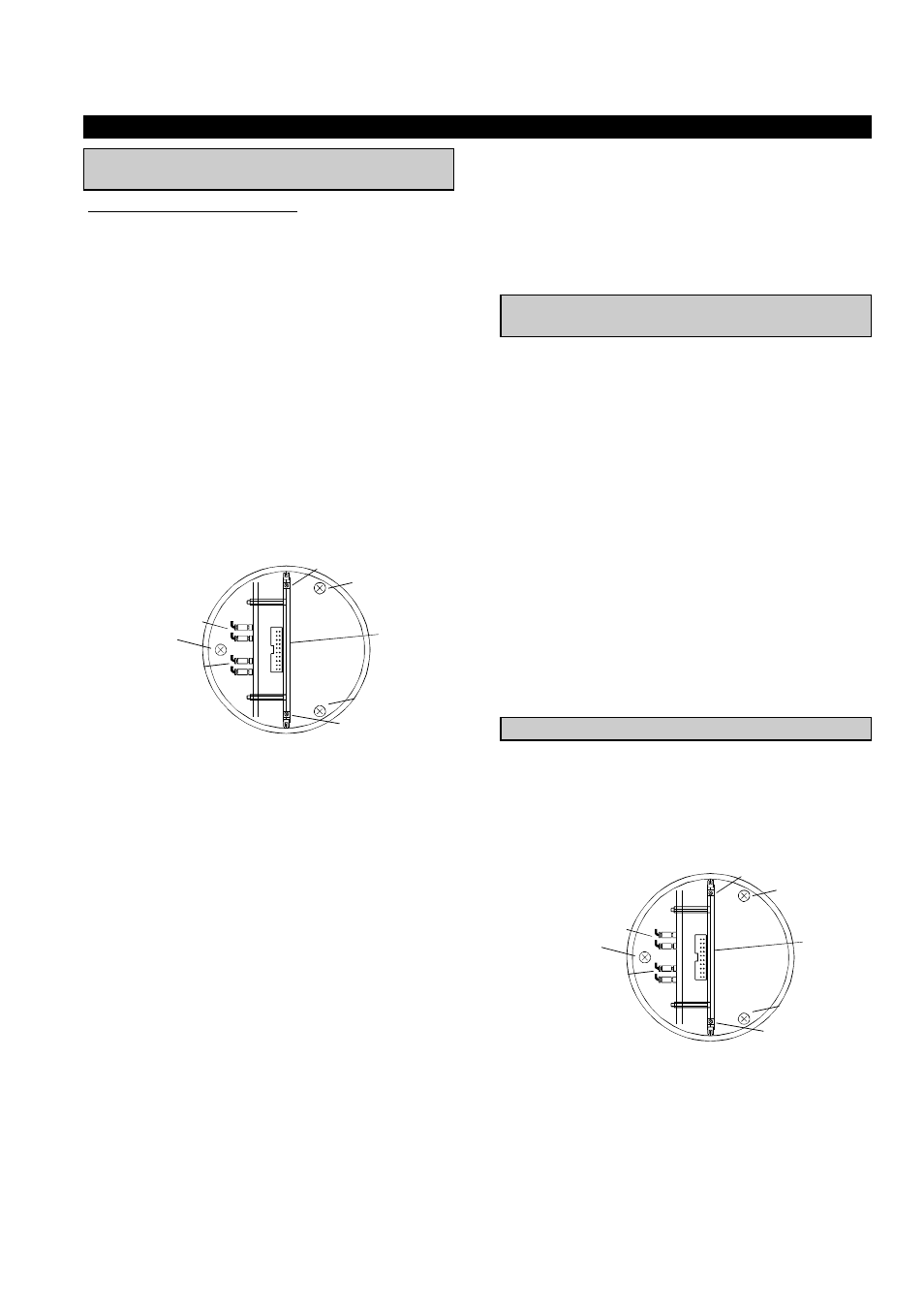
5.
Remove screws D using a screwdriver for recessed-
head screws [size 2, blade length min. 200 mm
(8”)] and carefully remove the complete electronics.
6.
Remove plug CO 1/2 or CO 1/2 + CO 3/4
(depending on flowmeter version).
7.
On the new electronic unit, check the power supply
voltage and fuse F1 and change over /replace if
necessary, see sect. 8.3.
8.
Reassemble in reverse order (points 6 to 1).
Important: Ensure that the screw thread of the covers on
the electronic and terminal compartment is
well greased at all times.
Following only applies for UFC 500... signal converter.
9. All data must be reset after replacement of the
electronic unit. The supplied report on settings
contains the standard factory setting. The customer-
specific data should be recorded in the report before
setting as described in sect. 4 + 5.
10. Subsequently be sure to check the zero and store the
new zero value, see sect. 7.2 and fct. 1.1.4.
8.2
Replacement of primary head in separate
systems
Always switch off power source before commencing
work!
•
Specific calibration data for each primary head are
determined during factory calibration. The primary
head constant GK is specified on the nameplate.
•
New data must be set when a primary head is
replaced.
UFC 400 F signal converter
New setting by KROHNE Service personnel.
UFC 500 F signal converter
•
Internal totalizer as described in sect. 5.6. Note down
totalizer counts beforehand.
•
Enter value of path lengths in fct. 5.3.2 and 5.3.3 (in
service menu).
•
Enter value of primary constant GK in fct. 3.1.6.
•
If the new primary head has a different meter size,
this must be set under fct. 3.1.5. Also the full-scale
range for Q
100%
must be changed in fct. 3.1.1 (for F/R
operation see also fct. 3.1.2 and 3.1.3).
•
A zero check (fct. 1.1.4) is advisable following
setting of new data, see sect. 7.2.
8.3
Change of power fuse F1
Always switch off power source before commencing
work!
1. Use the special wrench to remove the cover from the
front compartment.
2. Remove screws A, fold display board to side, and
remove plug B (ribbon cable, display board). Not
applicable to UFC 400... signal converter!
3. Power fuse F1 is now accessible. It must be replaced
by the same type of fuse (see marking on fuse holder).
4. Reassemble in reverse order.
A
A
D
D
B
CO 1/2
CO 3/4
D
A
A
D
D
B
CO 1/2
CO 3/4
D