Liter, Part b signal converter ufc 500 – KROHNE UFM 500 EN User Manual
Page 12
12
Part B
Signal converter UFC 500 ...
4.
Operation of the signal converter
This section 4 is repeated in the form of pull-out condensed operating instructions (pages 17-20).
4.1
Operating and check elements
The operating elements are accessible after removing the cover of the electronics section using the special wrench.
Caution: Do not damage the screw thread, never allow dirt to accumulate, and make sure it is well greased at all times.
4.2
KROHNE operator control concept
4.2.1
Description
The operator control concept for the UFC 500... signal converter consists of 3 levels (horizontal), see below.
Setting level:
This level is subdivided into 3 main menus.
Fct. 1.0 OPERATION
:
This menu contains only the most important parameters and functions of
menu 3 to allow rapid changes to be made during the measuring mode.
Fct. 2.0 TEST: Test menu for checking the signal converter.
Fct. 3.0 INSTALL.: All flow measurement- and flowmeter-specific parameters and functions can be
set in this menu.
Parameter check
Fct. 4.0 PARAM.ERROR: This level is not selectable. After exiting from the “setting level”, the
level:
signal converter checks new data for plausibility (inconsistency). If an error is established, the signal
converter reverts to menu 4. In this menu, all functions can be scanned and those, that are
inconsistent, changed.
Reset/acknowledge This menu has two tasks and is selected via Entry Code 2 (
↵↑→
), see sect. 4.2.5
level:
1) Separate resetting of totalizers, provided that resetting is enabled by setting “YES” under fct.
3.6.10 ENABL.RESET.
2) Error scanning and acknowledgment (Quit)
Errors that have occurred since the last acknowledgment are indicated in a list. After
acknowledgment and elimination of the cause(s), these errors are deleted from the list.
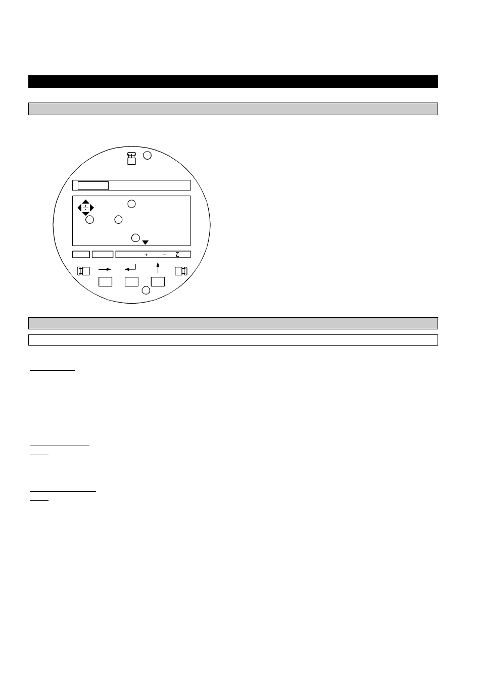
U F C500
KR OHNE
flow r ate
s oni c vel o.
total
49627
Liter
4
3
2
6
1
5
①② Display 1
st
(top) and 2
nd
(middle) lines.
③ Display 3
rd
(bottom) line: Arrows (▼) to
identify actual display.
Flowrate
actual flowrate
Sonic.velo Sound velocity
+
Totalizer (Forward flow)
-
Totalizer (Reverse flow)
Σ
Sum totalizer (+ and -)
④
Keys for setting the signal converter, refer to
“Setting diagram” (on the right) and sect.
4.2.2
⑤
Magnetic sensors to set the converter by
means of a hand-held bar magnet (optional)
without having to open the housing, refer to
sect. 6.4. Function of sensors same as keys ④.
⑥
Compass field, see sect. 4.4.