Table 3-5. max/min settings menu (continued), Max/min settings menu -16, R. 3.3.4) – KEPCO BOP 1KW-MG Operator Manual, Firmware Ver.2.48 to 3.04 User Manual
Page 80: Able 3-5)
3-16
BOP HIPWR 101509
3.3.4
CHANGING MAXIMUM OR MINIMUM SOFTWARE-CONTROLLED LIMITS
The maximum or minimum allowable voltage and current settings of the unit can be reduced
from the nominal using the Max/Min Settings menu. which lists the system’s software-controlled
voltage and current limits (+Voltage Max, –Voltage Min, +Current Max, –Current Min) as well as
the corresponding protection limits organized by operating mode. The default values of the sys-
tem limits are established by the Model: the nominal (rated) values for voltage and current and
1.01 x the nominal (rated) values for protection. The default values can be reduced by modifying
the highlighted parameter. The unit will not accept local or remote commands that exceed the
system limits. The system limits are always in effect, even when the unit is controlled by an
external reference. If system limits are changed, the protection limits must be changed to
correspond to the new system limits. As an example, changing +Voltage Max and –Voltage
Min of a BOP 36-28MG to ±3V, respectively, causes the unit to behave as if it was a BOP 3-
28MG. In this case it is important to change the +V Protect Max and –V Protect Min limits (e.g.,
to ±3.3V, respectively) so that the load is protected when operating in Current Mode. System
limits are absolute values (do not use minus sign for negative limits).
The internal parameters +Current Protect Min and –Current Protect Max are displayed to com-
pletely define the permissible window when operating in Voltage mode. Similarly, +Voltage Pro-
tect Min, and –Voltage Protect Max are displayed to completely define the permissible window
for voltage when operating in Current mode.
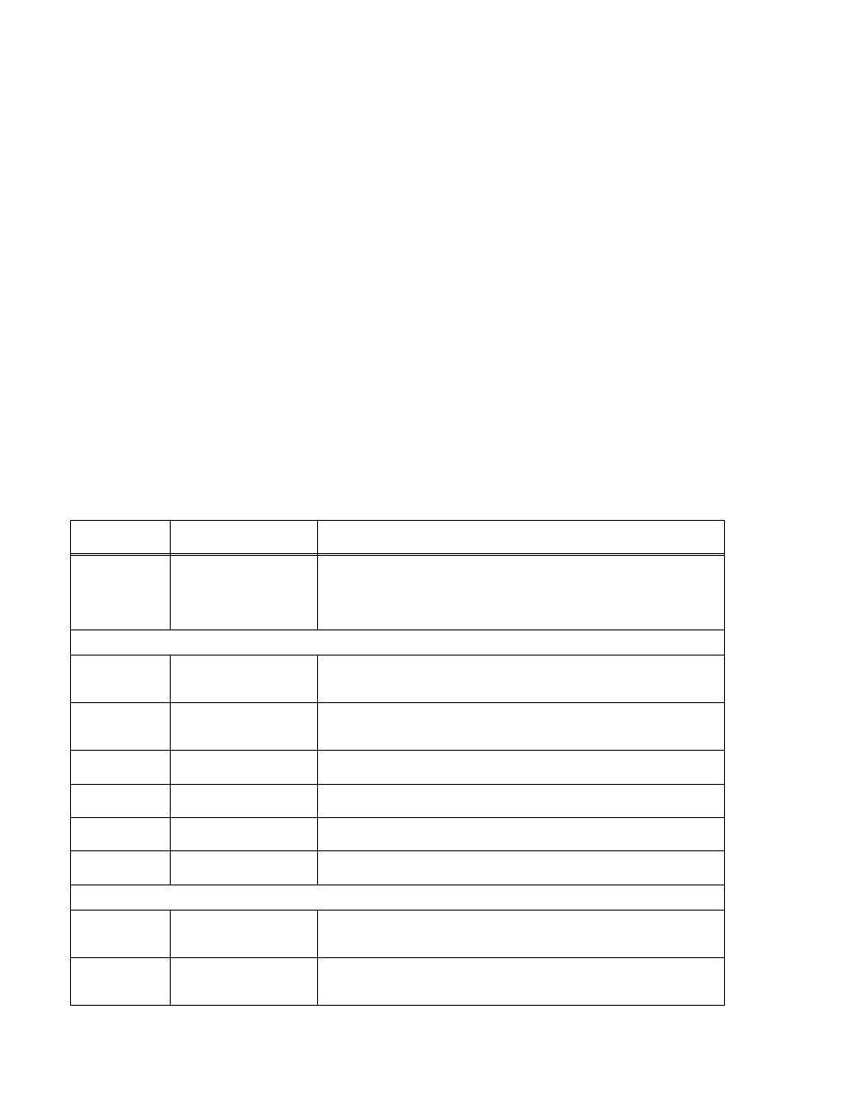
TABLE 3-5. MAX/MIN SETTINGS MENU
SETTING
CHOICES
(BOLD = Factory Default)
FUNCTION
Protect Entry
BIPOLAR
INDEPENDENT
BIPOLAR - Causes a single protection limit value (one for voltage, one for cur-
rent) to apply to both ± limits. Only one value is displayed and edited from the
front panel. (see PAR. 3.3.3.1.)
INDEPENDENT - Allows + and – protection limits to be set independently. from
the front panel (see PAR. 3.3.3.1 for considerations when using remote mode).
VOLTAGE MODE
+Voltage Max
(value)
+Eomax
Defines the maximum voltage level that can be set in voltage mode. Default =
Rated +Output voltage (e.g., for BOP 36-28MG, Eomax = 36). To modify, see
PAR. 3.3.4.1.
–Voltage Min
(value)
–Eomax
Defines the minimum (maximum negative) voltage level that can be set in volt-
age mode. Default = Rated –Output voltage (e.g., for BOP 36-28MG, Eomax =
36). To modify, see PAR. 3.3.4.1.
+C Protect Max
(value) model specific
up to Iomax + 1% of Iomax
Defines the maximum value for +Current Protect. To modify refer to 3.3.4.1.
+C Protect Min
(internal value)
Not Adjustable
Defines the minimum value that +Current Protect can be set to. This is a calcu-
lated value and is not adjustable from the front panel.
–C Protect Max
(internal value)
Not Adjustable
Defines the maximum (minimum negative) value that –Current Protect can be
set to. This is a calculated value and is not adjustable from the front panel.
–C Protect Min
(value) model specific
up to Iomax + 1% of Iomax
Defines the minimum (maximum negative) value for –Current Protect. To modify
refer to 3.3.4.1.
CURRENT MODE
+Current Max
(value)
+Iomax
Defines the maximum current level that can be set in current mode. Default =
Rated +Output current (e.g., for BOP 36-28MG, Iomax = 28). To modify, see
PAR. 3.3.4.1.
–Current Min
(value)
–Iomax
Defines the minimum (maximum negative) current level that can be set in current
mode. Default = Rated –Output current (e.g., for BOP 36-28MG, Iomax = 28). To
modify, see PAR. 3.3.4.1.